Dehydrating and drying device for chemically plated small shaft

A drying equipment, dehydration and drying technology, applied to chemical instruments and methods, cleaning methods using liquids, cleaning methods and utensils, etc., can solve problems affecting product quality, interfering with production, costing time and money, etc., to improve product quality , to ensure product quality, the effect of uniform drying temperature

Inactive Publication Date: 2012-06-06
浙江飞达利恩精密制造有限公司
View PDF0 Cites 0 Cited by
  • Summary
  • Abstract
  • Description
  • Claims
  • Application Information

AI Technical Summary

Problems solved by technology

[0005] (2) When the small shaft is dried, it is placed on the mesh belt of the mesh belt dryer. During the entire drying process, the position of the small shaft on the mesh belt is relatively fixed, and the temperature of the upper surface of the shaft body and the contact with the mesh belt There are still differences in the bottom layer, the drying temperature is not uniform enough, and the defects existing during dehydration cause water traces and yin and yang surfaces with different gloss on the surface of the small shaft body after drying, which seriously affects the product quality
[0006] (3) Poor product quality due to unclean dehydration and uneven drying temperature. When the finished product leaves the factory for a period of time and the user opens the package for assembly, they will find tiny rust spots and yellow spots on the surface of the shaft, especially during the rainy season. It is more serious, which leads to disputes such as return and repair, which is costly and time-consuming, and seriously interferes with normal production

Method used


Image

  • Dehydrating and drying device for chemically plated small shaft
  • Dehydrating and drying device for chemically plated small shaft
  • Dehydrating and drying device for chemically plated small shaft

Examples


Embodiment Construction

[0026] The following descriptions are only preferred embodiments of the present invention, and therefore do not limit the protection scope of the present invention.

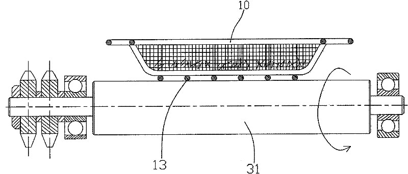
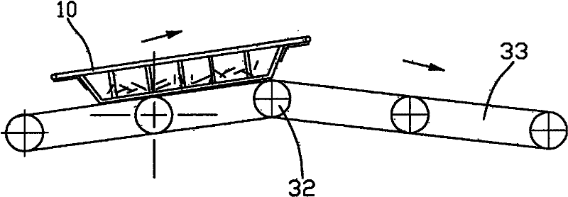
[0027] see attached Figures 2 to 6 Shown: the dehydration and drying equipment of the electroless plating small shaft of the present invention includes a dehydration drying basket 10, a shaking type rapid dehydration device 20, and a drum type dynamic drying device 30, wherein, the dehydration drying basket 10 inner substrate part The flat stainless steel wire mesh 11 is provided with stainless steel support plates 12 on both sides; the shaking type rapid dehydration device 20 is composed of a bracket 21, a roller slideway 22, a centrifugal type dehydrating fan 23, and a shaking mechanism 24. Among them, the dehydration drying basket 10 Placed on the roller slideway 22 supported by the bracket 21, two centrifugal dewatering fans 23 are arranged below the roller slideway 22, and a proximity switch 25 is respectiv...


PUM


Abstract

The invention discloses a dehydrating and drying device for a chemically plated small shaft, which comprises a dehydrating and drying basket, a shaking type quick dehydrating device and a drum-type dynamic drying device. The dehydrating and drying basket is lined with a stainless steel net inside; the shaking type quick dehydrating device comprises a bracket, a trolley slideway, a centrifugal dehydrating fan and a shaking mechanism, wherein the dehydrating and drying basket is arranged on the trolley slideway supported by the bracket, the centrifugal dehydrating draught fan is arranged below the trolley slideway, the shaking mechanism is matched with the dehydrating and drying basket; and the drum-type dynamic drying device comprises a bracket, drums, a transmission chain, a drying box, a heating tube, a fan, an electronic control cabinet and a driving component, wherein the drums are connected together by the transmission chain, the transmission chain is driven by the driving component, the drying box is arranged above the transmission chain, the heating tube is arranged inside the drying box, and the fan and the electronic control cabinet are arranged outside the drying box. The invention can completely dehydrate the chemically plated small shaft and can ensure even drying temperature at the same time.

Description

Technical field: [0001] The invention relates to the technical field of post-processing equipment for electroless nickel plating products, in particular to a dehydration and drying equipment for small shafts after electroless nickel plating. Background technique: [0002] At present, the small shaft after electroless nickel plating is generally cleaned with pure water, then picked up from the water tank, wrapped with nylon gauze into a ball and placed in a barrel drying machine, and the water is dried by the centrifugal force of the high-speed rotation of the drying barrel. (Similar to spin drying in a washing machine). Then, the dehydrated small shaft is flattened in the mesh belt dryer for drying treatment, and then packaged and shipped out after cooling. [0003] The above-mentioned existing process operations and equipment have the following defects: [0004] (1) Dehydration is difficult to completely clean, especially in the central part after the nylon gauze bandage,...

Claims


Application Information

Patent Timeline
Patent Type & Authority Patents(China)
IPC IPC(8): B08B3/02
Inventor 夏建民
Owner 浙江飞达利恩精密制造有限公司
Why Eureka
Try Eureka