Capacitance diaphragm gauge and vaccum apparatus

一种电容式、真空计的技术,应用在测量装置、利用电容变化的流体压力测量、通过电磁元件测量流体压力等方向,能够解决隔膜真空计成本增加等问题,达到低成本的效果

Active Publication Date: 2012-01-04
CANON ANELVA CORP
View PDF1 Cites 0 Cited by
  • Summary
  • Abstract
  • Description
  • Claims
  • Application Information

AI Technical Summary

Problems solved by technology

This inevitably leads to an increase in the cost of the diaphragm vacuum gauge itself

Method used


Image

  • Capacitance diaphragm gauge and vaccum apparatus
  • Capacitance diaphragm gauge and vaccum apparatus
  • Capacitance diaphragm gauge and vaccum apparatus

Examples


Embodiment Construction

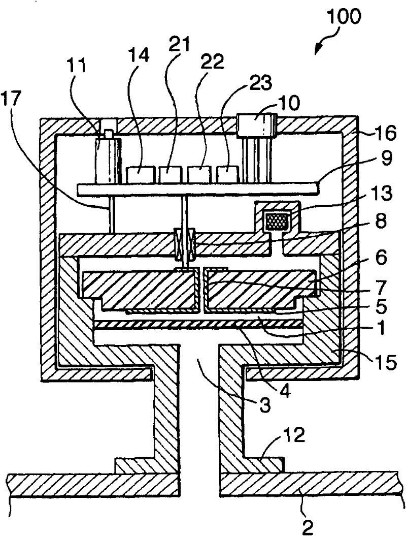
[0037] The best mode for carrying out the present invention will be described in detail below with reference to the accompanying drawings. figure 1 is a schematic cross-sectional view showing one embodiment of the capacitive diaphragm vacuum gauge according to the present invention. and figure 1 The same reference numbers in Figure 5 Indicates the same parts.

[0038] exist figure 1 On the circuit board 9 shown in , the zero point adjustment potentiometer 11, the inclination angle sensor 14, the capacitance detection unit 21, the pressure correction unit 22 and the storage unit 23 are fixed. figure 1 and Figure 5 The difference is that the capacitive diaphragm vacuum gauge includes an inclination angle sensor 14 and a storage unit 23 . The pressure correction unit 22 and the storage unit 23 correct the pressure measurement value based on the inclination angle of the capacitive diaphragm vacuum gauge 100 detected by the inclination angle sensor 14, which will be descri...


PUM

PropertyMeasurementUnit
capacitanceaaaaaaaaaa

Abstract

A capacitance diaphragm gauge includes an inclination angle sensor which detects the inclination angle of the gauge. The pressure dependences of capacitance obtained when the capacitance diaphragm gauge is mounted on a vacuum apparatus at the first inclination angle (+90 DEG ), the second inclination angle (0 DEG ), and the third inclination angle (-90 DEG ) are stored in a storage unit in advance. A pressure measurement value is then corrected based on the inclination angle information detected by the inclination angle sensor and the capacitance-pressure characteristic data is actually measured at the first, second and third inclination angles, and stored in the gauge.

Description

technical field [0001] The present invention relates to a capacitive diaphragm vacuum gauge and a vacuum device for pressure measurement, in particular to a capacitive diaphragm vacuum gauge suitable for pressure measurement in a vacuum device such as a sputtering device or an etching device. Background technique [0002] Figure 5 is a view schematically showing a capacitive diaphragm vacuum gauge disclosed in the specification of US Patent No. 4,785,669. refer to Figure 5 , reference numeral 100 denotes a capacitive diaphragm vacuum gauge for measuring the pressure inside the vacuum device 2 ; and reference numeral 16 denotes a case covering the capacitive diaphragm vacuum gauge 100 . The case 16 contains the getter 13, the insulating member 6, the fixed electrode 5, the circuit board 9, and the like. [0003] The conductive housing 15 contains a reference pressure chamber (vacuum-sealed chamber) 1 which is sealed while being kept at a high vacuum by a getter 13 . The r...

Claims


Application Information

Patent Timeline
Patent Type & Authority Patents(China)
IPC IPC(8): G01L9/12
CPCG01L9/0072G01L19/0092G01L19/02
Inventor 宫下治三
Owner CANON ANELVA CORP
Why Eureka
Try Eureka