Chip card connector

A chip card and connector technology, which is applied in the direction of connection, parts of the connection device, and a device for preventing wrong connection, etc., can solve problems such as damage to electronic devices, current loops, damage to the chip card connector 100, and improve convenience Effect

Inactive Publication Date: 2010-07-14
E-TEN
View PDF0 Cites 5 Cited by
  • Summary
  • Abstract
  • Description
  • Claims
  • Application Information

AI Technical Summary

Problems solved by technology

In this way, a current loop will be generated between the power pin 150a and the signal pin 160a or 160b, resulting in a short circuit between the power pin 150a and the signal pin 160a or 160b
Similarly, removing the chip card 50 when the mobile phone is turned on will also cause the above-mentioned short circuit phenomenon, and then damage the chip card co

Method used


Image

  • Chip card connector
  • Chip card connector
  • Chip card connector

Examples


Example Embodiment

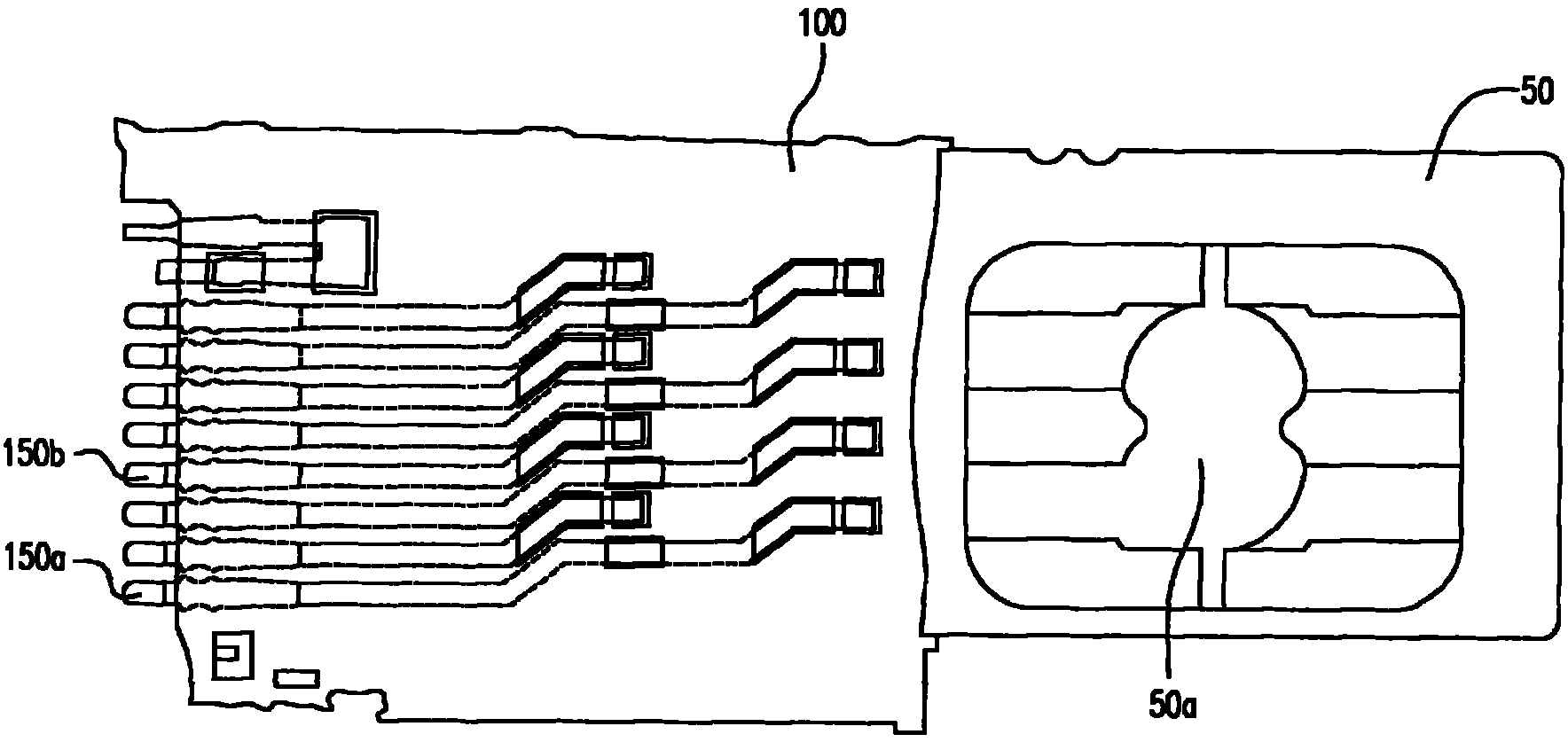
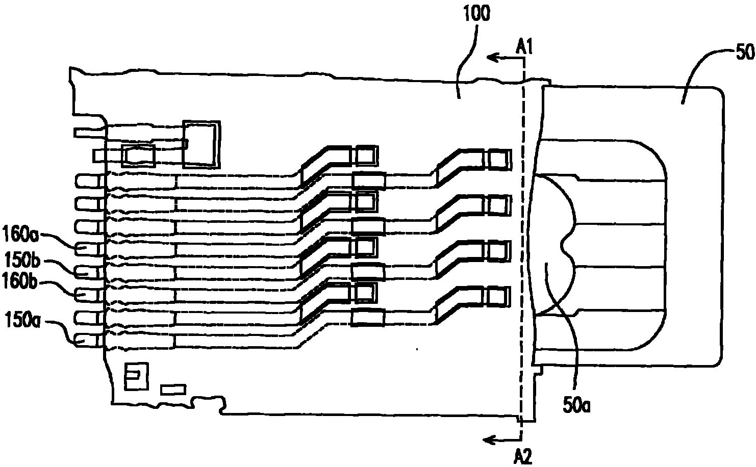
[0058] figure 2 It is a top view of a chip card connector according to an embodiment of the present invention. Please refer to figure 2 The chip card connector 200 of this embodiment includes a body 210, a metal cover 220, a first power pin 230, a second power pin 240, a third power pin 250, and a detection pin 260 With multiple signal pins 270a, 270b, 270c, 270d, 270e and 270f. The main body 210 has a accommodating groove 210 a for receiving the chip card 280, and the metal cover 220 covers the main body 210. The chip card 280 has a plurality of power pads 280a and 280b, and a plurality of signal pads 280c, 280d, 280e, 280f, 280g, and 280h. The first power pin 230, the second power pin 240, the third power pin 250, and the detection pin 260 are all configured to the body 210, wherein one end of the second power pin 240 and one end of the third power pin 250 are respectively It protrudes from the receiving groove 210a.

[0059] When the chip card 280 is inserted into the acc...


PUM


Abstract

The invention discloses a chip card connector, which is suitable for being arranged on a circuit board having a power supply terminal and a grounded terminal and the chip card is provided with a plurality of power supply pads and a plurality of signal pads. The chip card connector comprises a body, a metal cap body, a first power supply pin, a second power supply pin, a third power supply pin, a detection pin and a plurality of signal pins. The body is provided with an accommodating groove, and the metal cap body is electrically connected with the grounded terminal and covers the body. On end of the first power supply pin is electrically connected with the power supply terminal. One end of the second power supply pin is used for coming into contact with one of the power supply pads; and one end of the third power supply pin is used for coming into contact with another one of the power supply pads. The detection pin is respectively electrically connected with the second power supply pin and the third power supply pin, and the signal pins are respectively used for coming into contact with the signal pads.

Description

technical field [0001] The invention relates to a connector, and in particular to a chip card connector. Background technique [0002] With the continuous advancement of science and technology in recent years, human life has become inseparable from various electronic products. Taking portable communication devices such as mobile phones as an example, the penetration rate of mobile phones is quite high nowadays, and almost every general consumer has a mobile phone. Some mobile phone users will have two or more door numbers at the same time for the needs of life and work, and the relevant data of each door number will be stored in a chip card, such as a Subscriber Identity Card (Subscriber Identity Card). Module card, SIM card). If the user wants to change the door number to communicate, he must first change the SIM card installed in the mobile phone before using another door number. [0003] At present, the general mobile phones on the market do not support the hot swappin...

Claims


Application Information

Patent Timeline
IPC IPC(8): H01R12/16H01R13/703H01R13/641
Inventor 庄孟杰
Owner E-TEN
Why Eureka
Try Eureka