Lower-body structure for automobile

A vehicle body and automobile technology, which is applied to the superstructure, vehicle components, and superstructure sub-assemblies, etc., can solve the welding joint fracture, the inability to fully exert the restraint performance of the seat belt on the occupant, and the reduction of the N support performance of the fuel tank, etc. problem, to achieve the effect of high binding force

Inactive Publication Date: 2010-07-14
TOYOTA SHATAI KK
View PDF1 Cites 10 Cited by
  • Summary
  • Abstract
  • Description
  • Claims
  • Application Information

AI Technical Summary

Problems solved by technology

[0010] However, in the existing construction, the combination of the insulating flange 43 of the fuel tank bracket 4 and the front of the rear beam 2 is the peeling direction relative to the seat belt load G, and the combination of the front half 1a of the floor 1 and the fuel tank bracket 4 is relatively safe. The belt load G is also the peeling direction, so when the seat belt load G is large, it is possible to break the joint of the fuel tank bracket 4 and the rear cross member 2, or the weld joint o

Method used


Image

  • Lower-body structure for automobile
  • Lower-body structure for automobile
  • Lower-body structure for automobile

Examples


Embodiment Construction

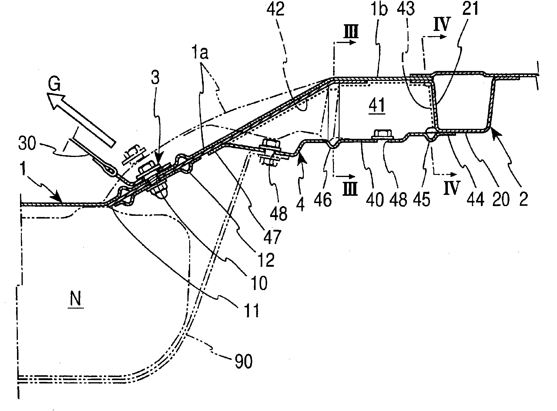
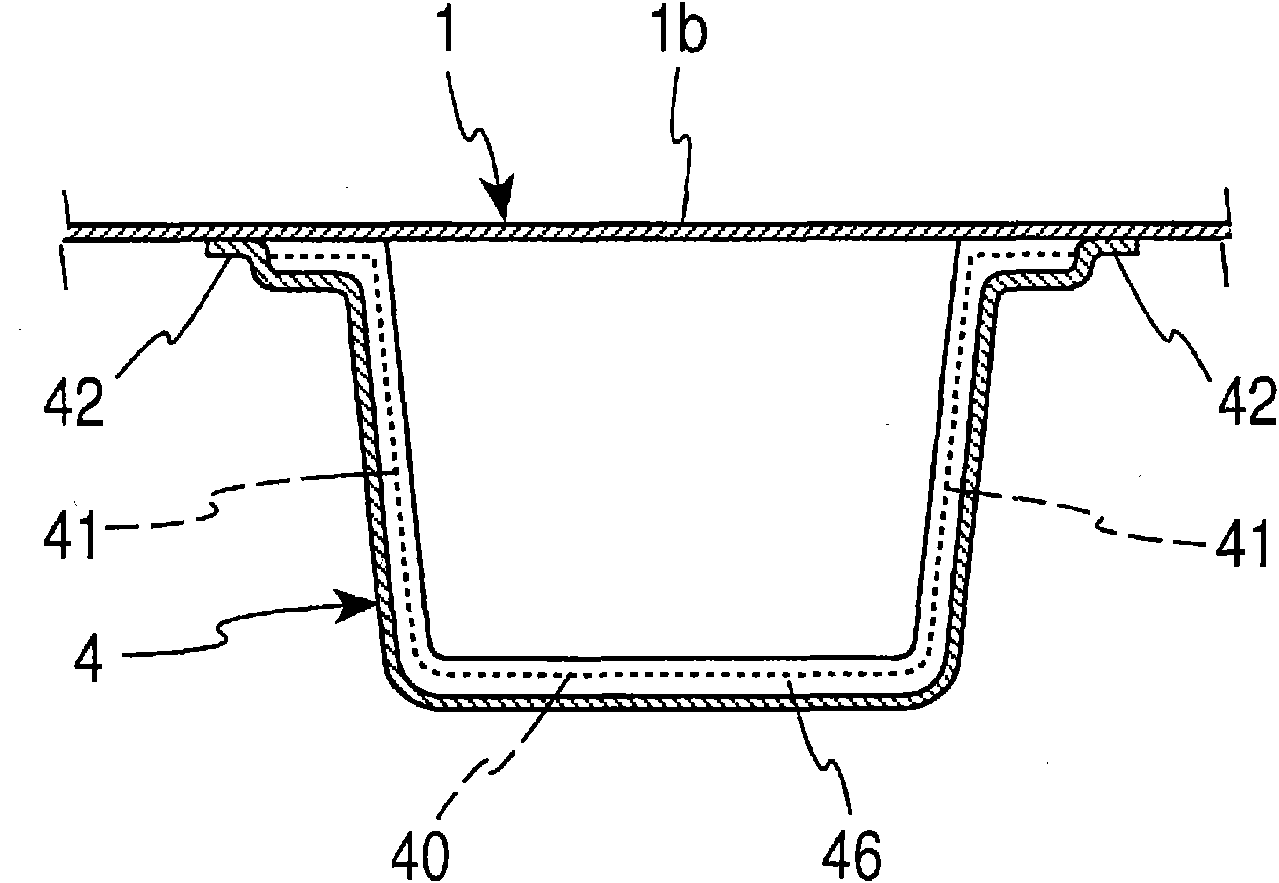
[0028] To apply the present invention to Figure 5 An embodiment of the floor 1 at the rear of the cab is shown for illustration. The basic structure of floor 1 is identical with existing structure in addition, as figure 1 As shown, on the floor 1, in the rear seat S ( Figure 5 ) and the installation position of the fuel tank N are formed with a front half 1a that extends slightly obliquely toward the rear and upward, and a horizontal flat shape that bends from the front half 1a and connects to the rear trunk floor that is one step higher. The second half of 1b.

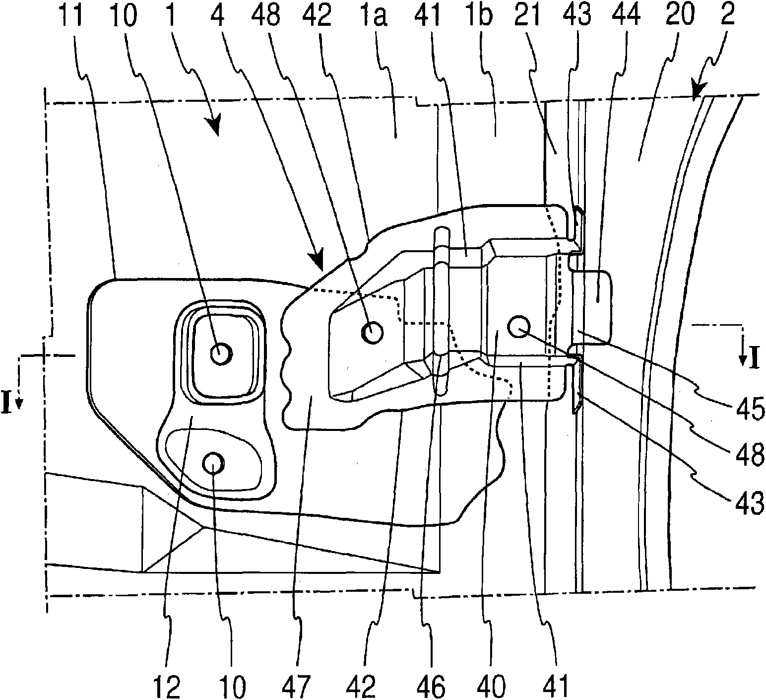
[0029] Such as figure 1 , figure 2 As shown, the seat belt buckle 3 for the rear seat is fastened with bolts at a lower position near the front end of the front half 1a. The seat belt buckle 3 uses a metal plate with a substantially L-shaped cross section, and one piece is overlapped with the upper surface of the front half 1a, and is bolted into the coupling hole 10 of the front half 1a for coupling. A seat ...


PUM


Abstract

Provided is an automobile lower body structure, which is highly strong against a seat belt load (G) to act from a seat belt anchor (3) joined to the floor (1) of a compartment rear portion. A tank bracket (4) for supporting a fuel tank (N) is disposed on that lower face of the floor (1) of the compartment rear portion, to which the seat belt anchor (3) is joined. The tank bracket (4) having a substantially inverse hat-shape section forms a closed section together with the floor (1). At the rear end, the rear edge flange (43) of a side wall (41) is joined to the front face of a floor cross member (2), and a joint flange (44) extended from the rear end of a bottom wall (40) is joined to the lower face of the floor cross member (2), thereby to enhance the bonding force to the floor cross member (2). In the bracket (4), beads (45 and 46) are formed to extend in the widthwise direction of the bracket (4), and are deformed to open longitudinally with respect to the seat belt load (G) when the vehicle abruptly decelerates, thereby to absorb the load (G), so that the portion of the floor (1) joining the seat belt anchor (3) is not moved by the load (G).

Description

technical field [0001] The present invention relates to an automobile underbody structure in which the periphery of a seat belt buckle installation portion of the floor at the rear of the cab is reinforced. Background technique [0002] Generally, in a car, rear seats are provided on the floor at the rear of the cab, and seat belt buckles for the rear seats are coupled to the floor. It also describes a structure in which a fuel tank bracket supporting a fuel tank is provided on the lower surface side of the floor corresponding to the seat belt buckle coupling position, and the seat belt buckle coupling position of the floor is reinforced by the fuel tank bracket. [0003] Such as Figure 5 As shown, on the floor 1 at the rear of the cab supported between left and right rockers 6, a three-seater rear seat S is arranged on the top, and a fuel tank N is supported on the lower side of the floor 1. [0004] Such as Figure 5 , Figure 6 As shown, on the floor 1 behind the insta...

Claims


Application Information

Patent Timeline
IPC IPC(8): B62D25/20B60K15/067B60R22/22
CPCB60K15/067B62D25/20B60K15/06B62D25/2027
Inventor 田口政行
Owner TOYOTA SHATAI KK
Why Eureka
Try Eureka