Fabric knitting method, and weft knitting machine

A flat knitting machine and knitted fabric technology, which is applied in the directions of knitting, weft knitting, textiles and papermaking, can solve problems such as breakage and bending of the needle guide, so as to prevent the needle from being caught and avoid the needle guide. damage effect

Inactive Publication Date: 2010-07-14
SHIMA SEIKI MFG LTD
View PDF2 Cites 1 Cited by
  • Summary
  • Abstract
  • Description
  • Claims
  • Application Information

AI Technical Summary

Problems solved by technology

Therefore, if knitting is continued in a state where the decorative yarn is caught, the slider of the open needle will be stretched to the side of the lock needle via the fancy twisted yarn, and the slider of the open needle may be bent or bent. damaged

Method used


Image

  • Fabric knitting method, and weft knitting machine
  • Fabric knitting method, and weft knitting machine
  • Fabric knitting method, and weft knitting machine

Examples


Embodiment 1

[0032]

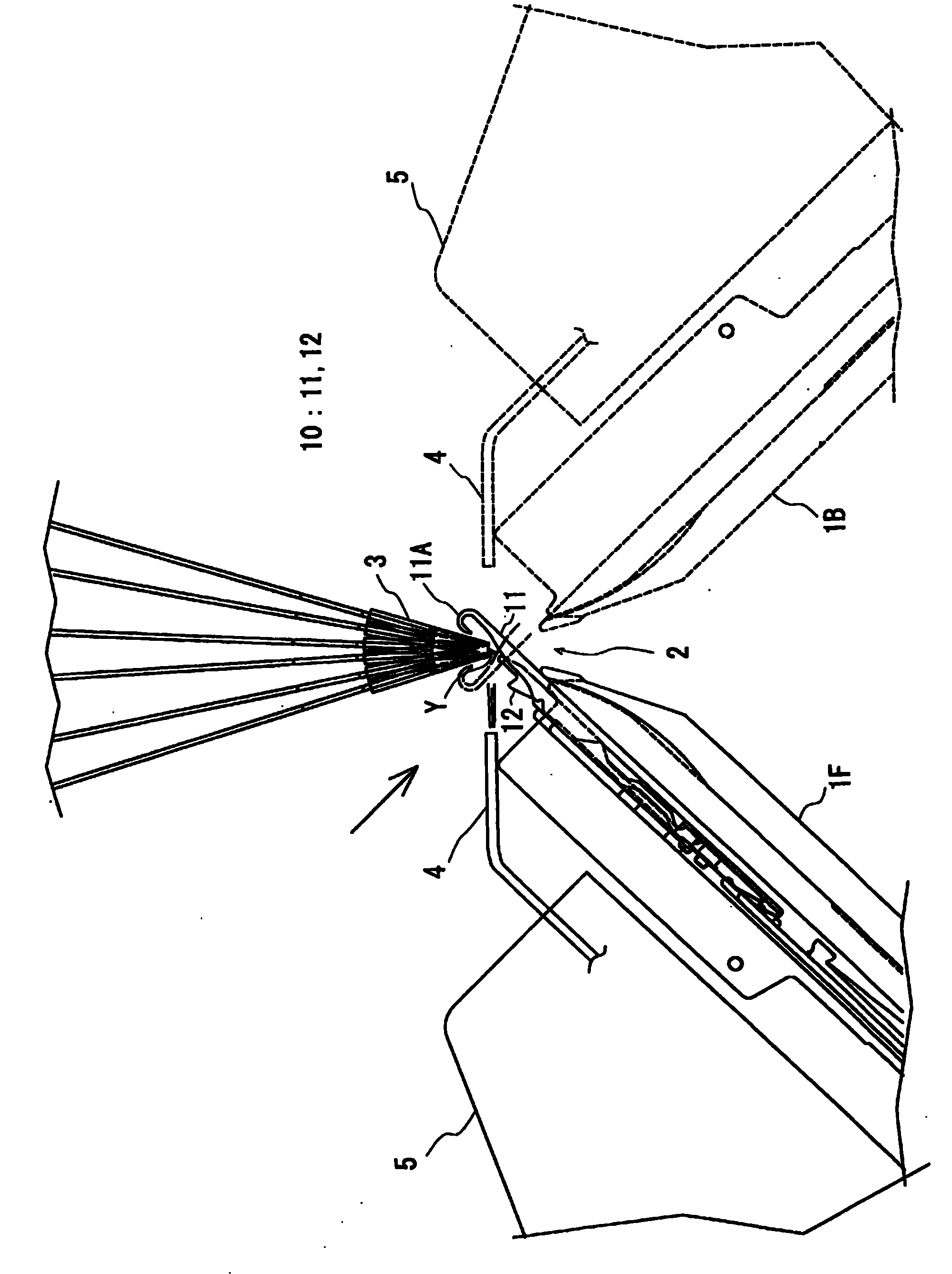
[0033] The flat knitting machine of this embodiment includes: a pair of needle beds 1F, 1B in which a plurality of compound needles 10 are arranged in a row; The air nozzle 4 that presses the decorative yarn portion Y1 that protrudes toward the outer periphery of the fancy twist yarn Y, and the carriage 5 that reciprocates in the longitudinal direction of the needle beds 1F, 1B. Below, based on figure 1 , 2 Each configuration of the flat knitting machine of this embodiment will be described in detail.

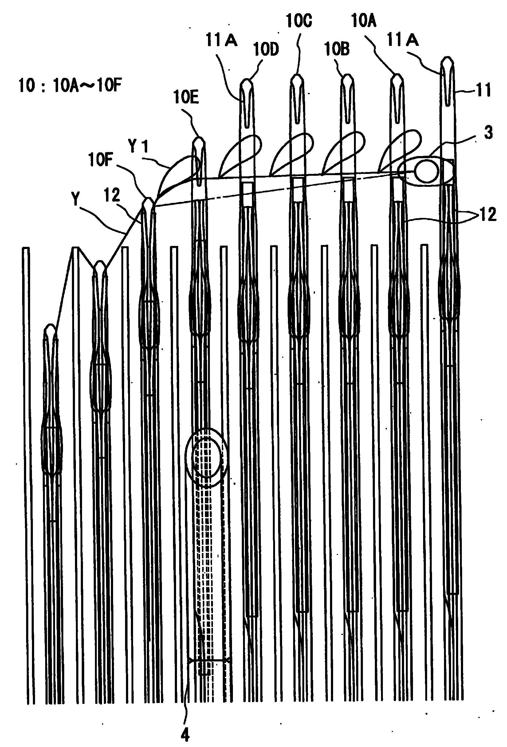
[0034] Such as figure 1 As shown, the compound needle 10 includes a needle body 11 and a slider 12 . The needle main body 11 has a hook portion 11A at its front end, and the slider 12 is, for example, a pair of thin plates fitted into a groove of the needle main body 11 . By the relative sliding of the needle body 11 and the slider 12 in the longitudinal direction, the hook portion 11A provided at the tip of the needle body 11 is opened and closed. Specifically,...

Embodiment 2

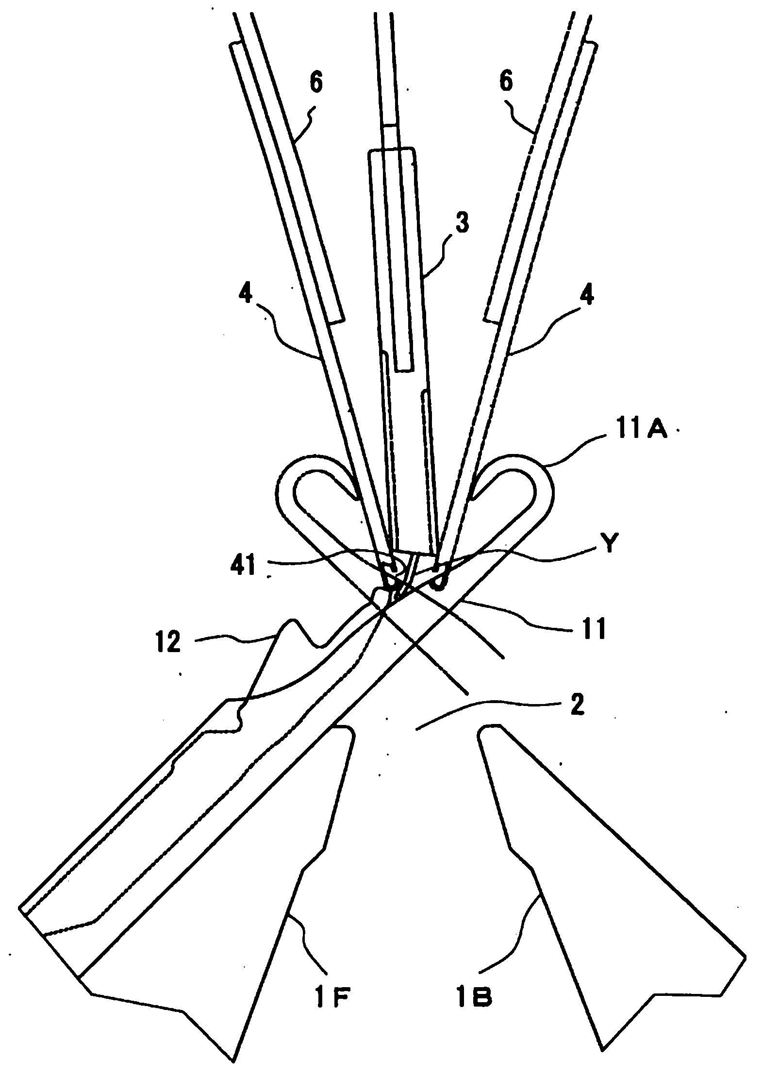
[0054] Next, based on image 3 An embodiment of the present invention in which an air nozzle is provided instead of a part of the yarn supplying member will be described. In this embodiment, the basic structure and functions are the same as those of the first embodiment, except that the structure and installation position of the air nozzles are different from those of the first embodiment. The following description will focus on the differences from the first embodiment.

[0055]

[0056] The yarn supply member 3 is slidably supported on a plurality of yarn guide rails (not shown) extending in the longitudinal direction of the needle bed substantially above the needle mouth portion 2 . The carrier rails are aligned in a direction perpendicular to the longitudinal direction of the needle beds 1F, 1B, and here, the nozzle brackets 6 are held using the carrier rails positioned at ends in the alignment direction, and the yarn supplying member 3 is held on the remaining yarn ca...


PUM


Abstract

Provided are a fabric knitting method and a weft knitting machine, which can prevent the decorative portions of designing twisted yarns from being caught by the sliders of composite needles. The weft knitting machine comprises a plurality of composite needles (10) each including a needle body (11) and a slider (12), a needle bed (1F) arraying those composite needles (10), and a feeding member (3) made reciprocative in the longitudinal directions of the needle bed for feeding a designing twisted yarn (Y) to the tooth portion (2) of the needle bed. The weft knitting machine is made operative to hook the designing twisted yarn (Y) fed to the tooth portion (2), on a hook (11A), and to pull the needle body into the needle bed (1F). The weft knitting machine further comprises an air nozzle (4) for injecting air at an angle of elevation higher than the horizon, thereby to hold the decorative portion protruding to the outer periphery of the designing twisted yarn (Y) fed, in the direction to leave the slider (12), so that the decorative yarn portion may not be hooked by the slider (12) when the needle body is pulled into the needle bed (1F), and a nozzle moving mechanism (or a carriage) (5) for reciprocating the air nozzle (4) along the longitudinal directions of the needle bed.

Description

technical field [0001] The present invention relates to a knitting method and a flat knitting machine for knitted fabrics capable of preventing decorative yarn portions of fancy twist yarns from being caught on sliders of compound needles. Background technique [0002] Conventionally, there is known a flat knitting machine using a compound needle including a needle body having a hook and a slider that opens and closes the hook (for example, Patent Document 1). In this flatbed knitting machine, the knitting yarn supplied from above the needle bed portion by the yarn supplying member is caught on the hook of the compound needle by causing the compound needle to enter and exit the needle bed portion from the facing needle beds sandwiching the needle bed portion. and pull it into the needle bed to knit the knitted fabric. At this time, the slider closes the hook with the retraction of the needle main body. [0003] Patent Document 1: International Publication No. WO2007 / 037285...

Claims


Application Information

Patent Timeline
Patent Type & Authority Applications(China)
IPC IPC(8): D04B15/56
CPCD04B15/56D04B15/96D04B1/16
Inventor 芦边伸介池中政光
Owner SHIMA SEIKI MFG LTD
Why Eureka
Try Eureka