
Gear shift controller for vehicle transmission

A transmission control and vehicle technology, which is applied in the direction of transmission control, toothed components, belts/chains/gears, etc., can solve the problems of vehicle violation, low braking effect, acceleration, etc., and achieve the effect of ensuring braking efficiency

Inactive Publication Date: 2010-07-14
ISUZU MOTORS LTD
View PDF2 Cites 17 Cited by
  • Summary
  • Abstract
  • Description
  • Claims
  • Application Information

AI Technical Summary

Problems solved by technology

For example, if the Figure 7 In the state of point C, the vehicle running at the second speed is accelerated on the downhill to the state of point D, and then the shift point of the upshift is exceeded to become the third speed, but at this time, the braking effect of the engine brake is low, As a result the vehicle accelerates further against the driver's will

Method used


Image

  • Gear shift controller for vehicle transmission
  • Gear shift controller for vehicle transmission
  • Gear shift controller for vehicle transmission

Examples


Embodiment Construction

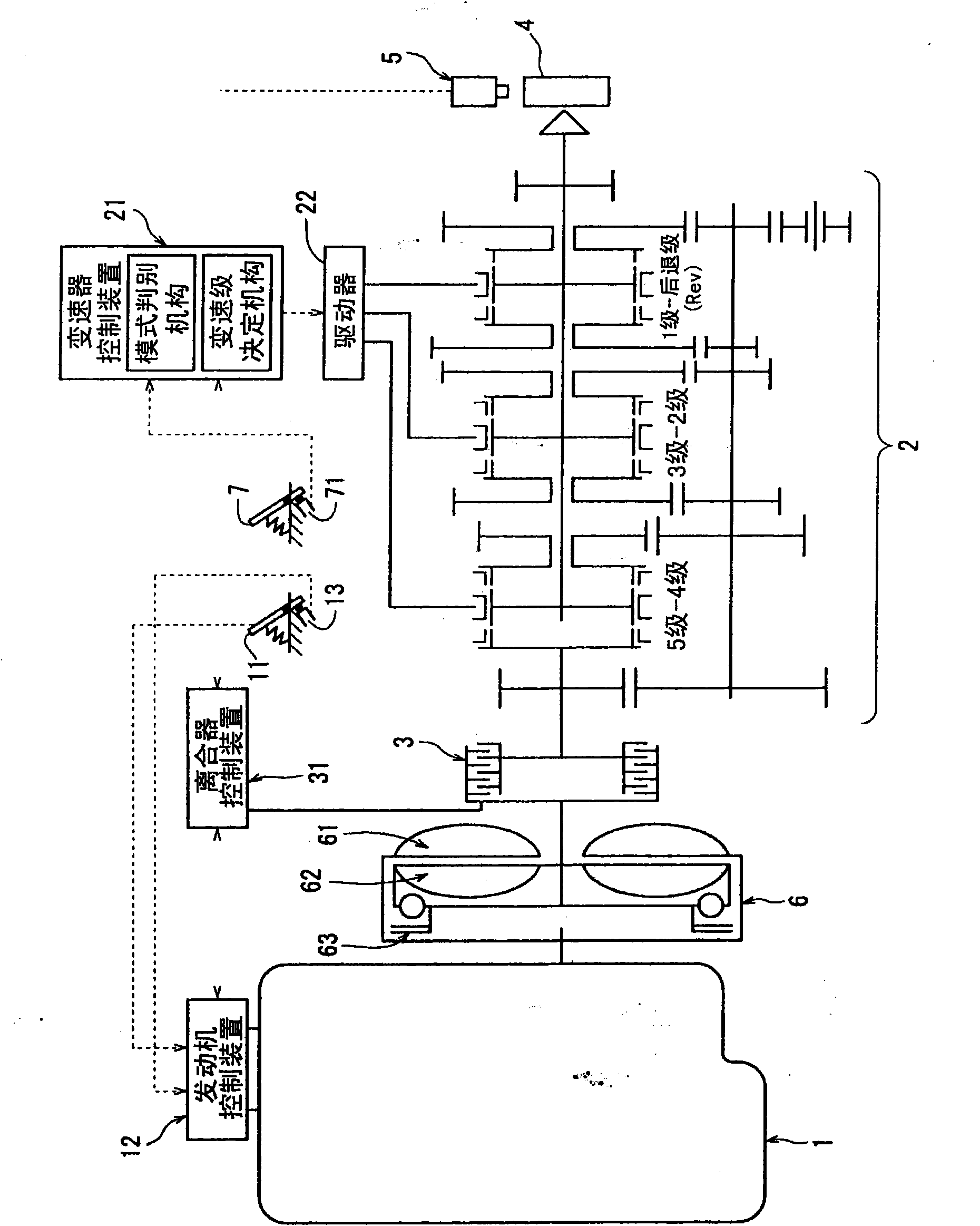
[0042] Hereinafter, an embodiment of a transmission control device according to the present invention will be described based on the drawings. figure 1 The embodiment of the present invention is an example of applying the present invention to a parallel-shaft gear mechanism type transmission with automatic transmission control. The basic structure of the power transmission device of the vehicle and the actions and Figure 6 shown unchanged from previous devices (in figure 1 in, for with Figure 6 Corresponding parts and the like are given the same reference numerals). That is, in the transmission control device 21 of the present invention, the signal from the vehicle speed sensor 5 and the signal of the accelerator opening degree of the engine (the amount of depression of the driver's accelerator pedal 11) are input, and by determining the vehicle speed and the accelerator opening degree corresponding to Figure 7 The same shift map determines the gear stage. When a shift ...


PUM


Abstract

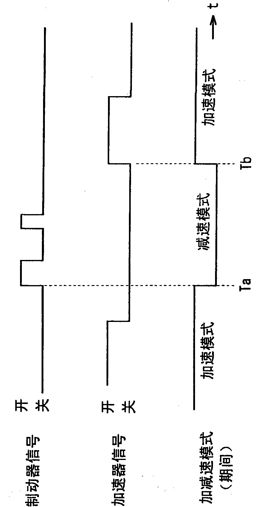
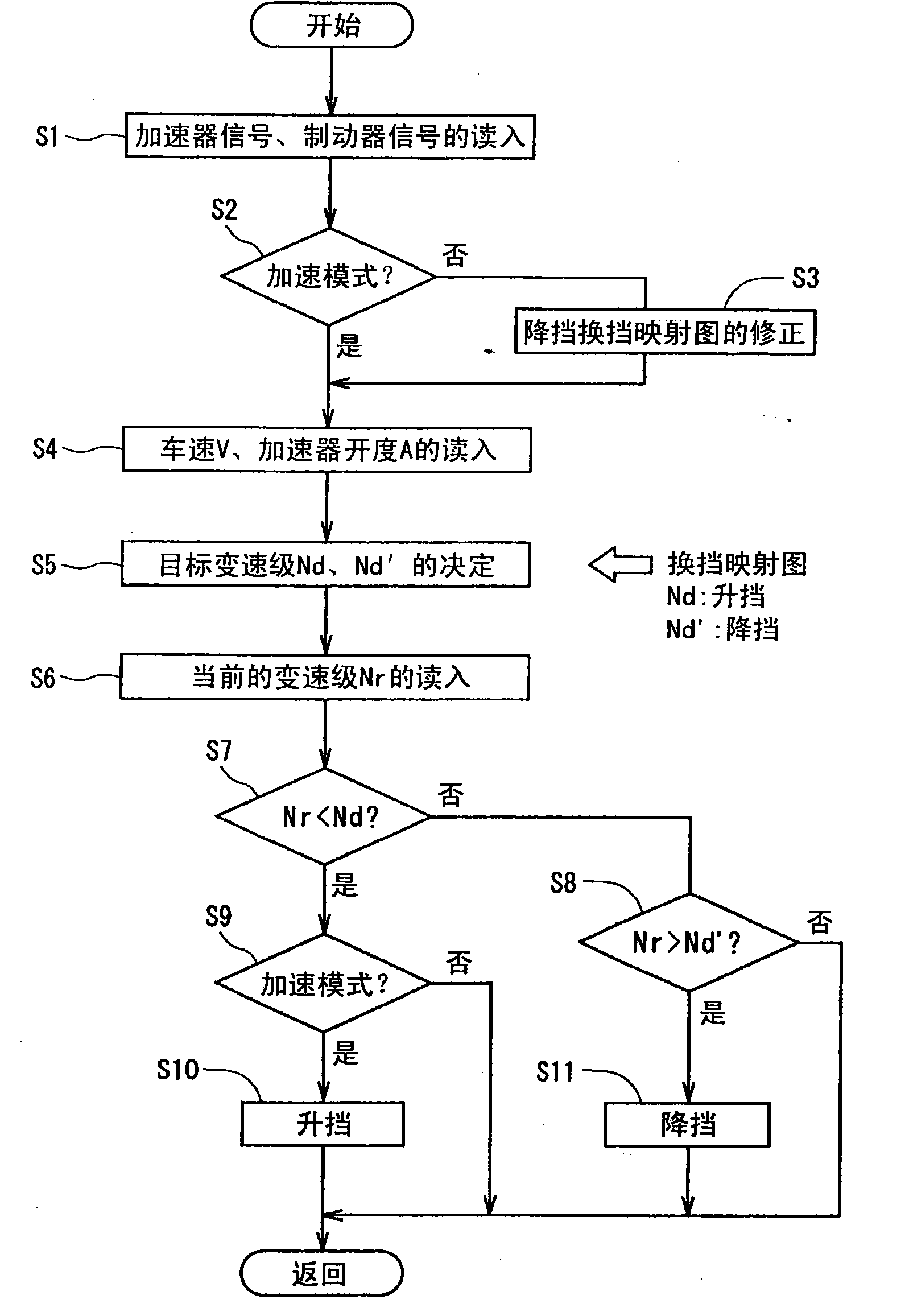
A gear shift controller for a vehicle transmission of a vehicle mounted with an engine and a transmission and capable of automatic transmission control by a shift map so as to shift the gear adequately for the vehicle traveling state and to ensure the braking force of the engine brake as intended by the driver while the vehicle speed is decreasing. The gear shift controller having a shift map for determining the gear according to the vehicle speed and the amount of accelerator pedal depression is provided with mode judging means for judging whether the mode period is an acceleration mode period or a deceleration mode period on the basis of the operation states of the accelerator pedal and the brake pedal. During the deceleration mode period after the driver depresses the brake pedal, shift-up is inhibited (S9), and the gear shift range of a shift-down map is corrected so as to vary the gear shift range in the vehicle speed increase direction (S2, S3) to perform shift-down early. With this, during the deceleration mode period, a braking force of the engine brake acts on the vehicle adequately, and the frequency of depressions of the brake pedal by the driver can be reduced.

Description

technical field [0001] The present invention relates to a transmission control device for automatically controlling a transmission position according to a running state of the vehicle in a vehicle equipped with a transmission having a plurality of transmission positions. Background technique [0002] In recent vehicles, automation of various devices has progressed, and regarding power transmission devices, various automatic power transmission devices for vehicles have been developed in order to facilitate driving of vehicles and reduce driver fatigue. An automatic transmission combining a torque converter and a planetary gear mechanism is a typical power transmission device, and it is widely used as a power transmission device of a so-called automatic transmission vehicle (AT vehicle). In addition to the automatic transmission, there is also a power that uses the same parallel-shaft gear mechanism transmission as the so-called manual transmission vehicle (MT vehicle), combin...

Claims


Application Information

Patent Timeline
Patent Type & Authority Applications(China)
IPC IPC(8): F16H61/16F16H59/18F16H59/44F16H59/54F16H59/66F16H61/682F16H61/68
CPCF16H61/682F16H59/18F16H61/21F16H61/0213F16H2061/0237F16H59/54
Inventor 山本康河西公幸窄智久阿部诚福永晋
Owner ISUZU MOTORS LTD
Learn More