
Agricultural binding device

A binding device, agricultural technology, applied in the fields of agriculture, application, plant support, etc., to achieve the effect of preventing the end of the binding belt from splitting, quickly connecting operations, and improving operation efficiency

Inactive Publication Date: 2010-07-21
赵南善
View PDF0 Cites 6 Cited by
  • Summary
  • Abstract
  • Description
  • Claims
  • Application Information

AI Technical Summary

Problems solved by technology

[0003] The present invention is proposed to solve the above-mentioned inconveniences in the past. By preventing damage to the binder or unnecessary consumption of straps that may occur during the operation of the binder, it prevents the waste of the binding belt, and uses a traction needle at the end of the belt supply part to draw out the binding. When strapping, prevent the end of the strap from splitting

Method used


Image

  • Agricultural binding device
  • Agricultural binding device
  • Agricultural binding device

Examples


Embodiment Construction

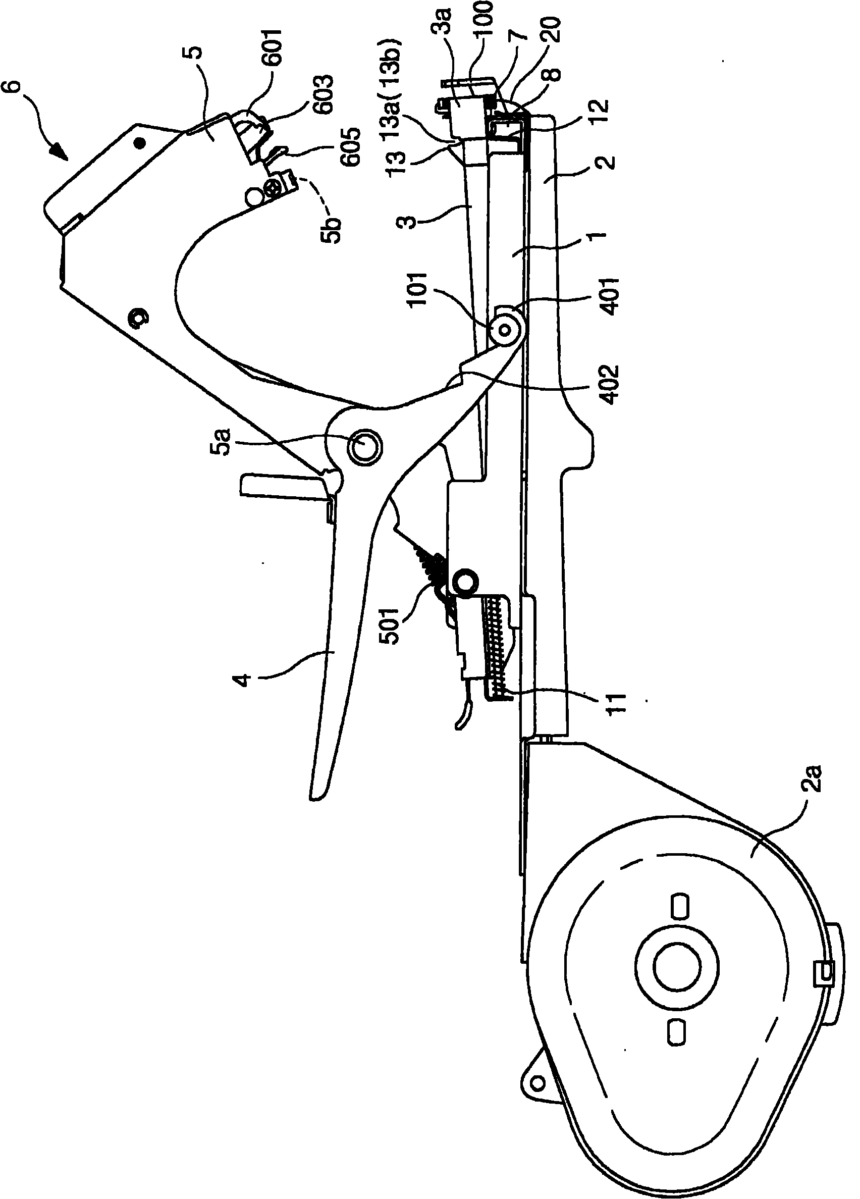
[0014] For the binding device with the following structure: a binding nail supply table 3 with binding nails 10 installed inside the binding device main body 1 is formed, and the binding nails are pushed by springs 11 to be supplied to the front-end connecting part 3a, and in the direction perpendicular to it The binding nail pressing out plate 12 is installed on the lower side, and a binding nail pressing outlet 3b is formed at the upper end opposite to it, so that a binding nail can be pushed out. There is a cut-off chamber 3c and a waiting room 8 outside the binding nail pressing outlet.

[0015] On one side of the bottom surface of the binder main body 1, there is a tape storage chamber 2a equipped with a tape reel, and on its opposite side, a tape supply portion 2 with a tape outlet 2b is formed to supply the binding tape 20 to the waiting tape chamber 8,

[0016] On the main body 1 of the binding device, the rotating shaft 5a is used to connect the lifting action body 5, ...


PUM


Abstract

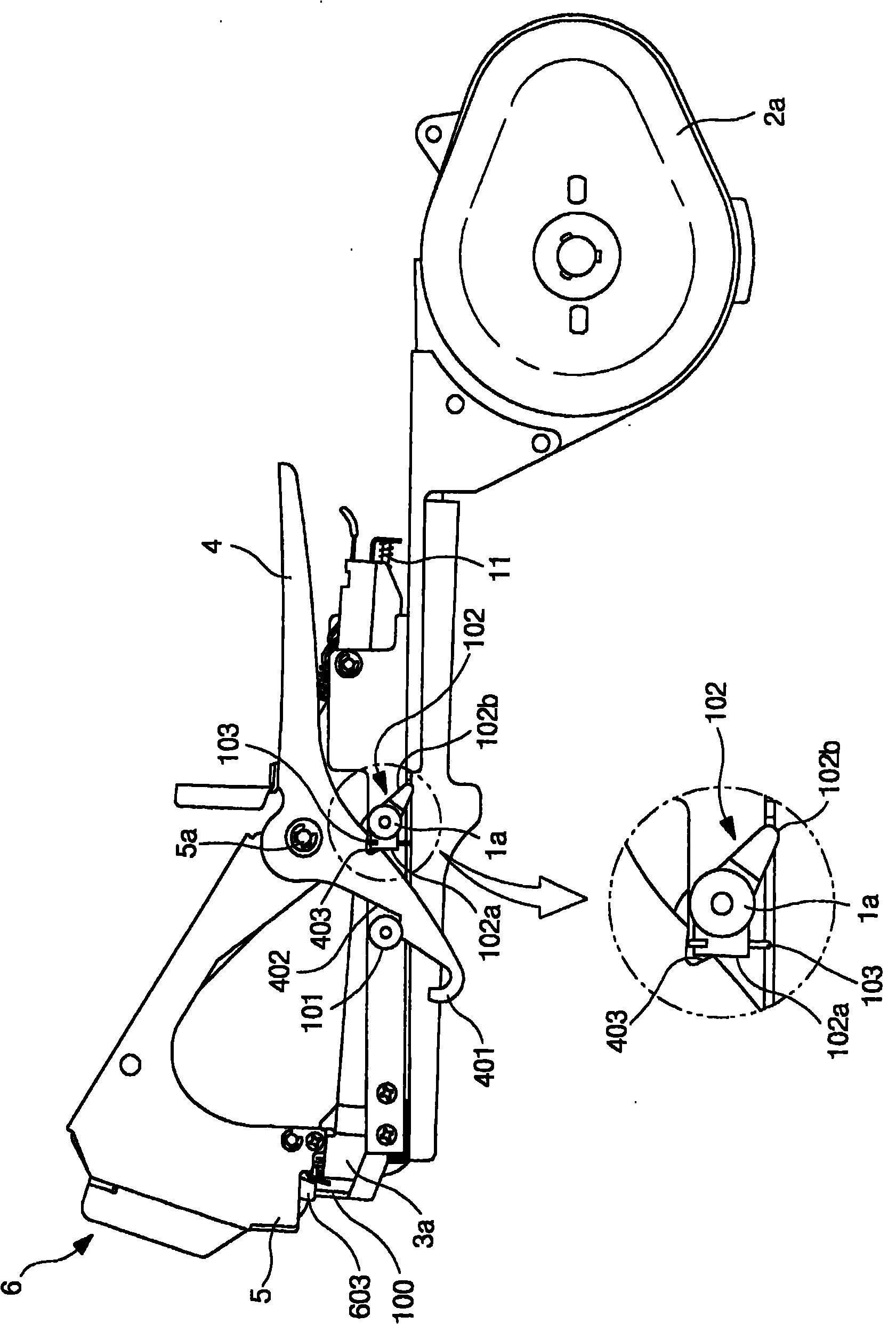
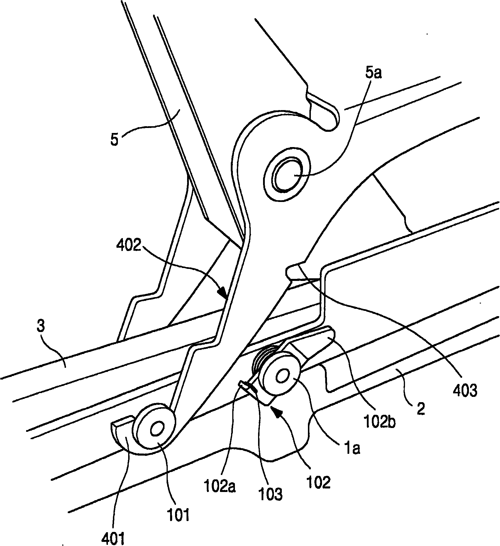
The invention relates to an agricultural binding device, in particular to the agricultural binding device used for binding vine shoots or crop straws and the like on a strut or a support rope. The binding device is characterized in that a clamping groove (403) is formed on the lateral surface of an operating rod (4) and a locking plate (102) is arranged on a main body (1) corresponding to the clamping groove (403) to form a locking device to make a bayonet part (102a) of the locking plate be combined with the clamping groove (403) of the operating rod; a support rope guiding groove is formed on the outer wall on both sides of a binding iron nail extrusion port to make the support rope passing through the upper surface of the binding iron nail extrusion port pass through when being clung to the upper surface of the binding iron nail extrusion port; and the elasticity of a traction needle is softer so as to prevent the clamped position from cracking when the traction needle clamps the tail end of a binding band for drawing the binding band.

Description

technical field [0001] The present invention relates to an agricultural binding device used when binding grape vines or crop stalks to support ropes. In terms of its composition: in order to prevent the action rod from shaking when the binding device is temporarily stopped in use, the action rod and A locking device is installed between the main bodies, and when the operation is temporarily stopped during the use of the binding device, the binding belt can be prevented from loosening; support rope guide grooves are made on the outer walls of both sides of the binding iron nail pressing outlet, so that it can pass through the binding iron nail pressing outlet. The supporting rope can be accurately connected by binding iron nails, so that the binding operation is more convenient; the elasticity of the pulling needle is made softer, and when the pulling needle clamps the end of the binding belt for pulling the binding belt, it prevents the clamped part from cracking , thus formin...

Claims


Application Information

Patent Timeline
IPC IPC(8): A01G17/08A01G9/12B65B27/10
Inventor 徐汉永
Owner 赵南善
Learn More