
Device and method for dredging discharge valve of polyurethane foam gap filler pot

A polyurethane foam and discharge valve technology, which is applied to the surface coating liquid device, spray device, coating, etc., can solve the problems of foam sealant tank discharge valve sticking, difficult to remove, and inconvenient to use. Achieve the effect of increasing service life, convenient installation and simple operation

Inactive Publication Date: 2010-07-21
上海威固化工制品有限公司
View PDF0 Cites 0 Cited by
  • Summary
  • Abstract
  • Description
  • Claims
  • Application Information

AI Technical Summary

Problems solved by technology

[0003] However, since polyurethane foam is very easy to solidify when it encounters air, and it is very difficult to remove after curing, the connection between the valve and the contact surface of the material liquid, that is, the discharge valve of the polyurethane foam caulk tank, often becomes sticky due to the solidification of polyurethane foam. Knot, causing inconvenience for the next use
In addition, if the polyurethane foam caulking agent tank itself is turned upside down or placed flat for a long time, it is also prone to sticking of the discharge valve of the foam caulking agent tank, which will affect normal use.
[0004] In the prior art, there is a cleaning agent specially used for polyurethane foam caulking agent, which is used to clean the residual polyurethane foam on tools such as spray guns. However, this cleaning agent can only be used for uncured foam. As far as the polyurethane foam on the discharge valve of the foam caulk tank is concerned, there is currently no effective means to remove it.

Method used


Image

  • Device and method for dredging discharge valve of polyurethane foam gap filler pot
  • Device and method for dredging discharge valve of polyurethane foam gap filler pot
  • Device and method for dredging discharge valve of polyurethane foam gap filler pot

Examples


Embodiment Construction

[0018] The present invention will be further described below in conjunction with embodiment and with reference to accompanying drawing:

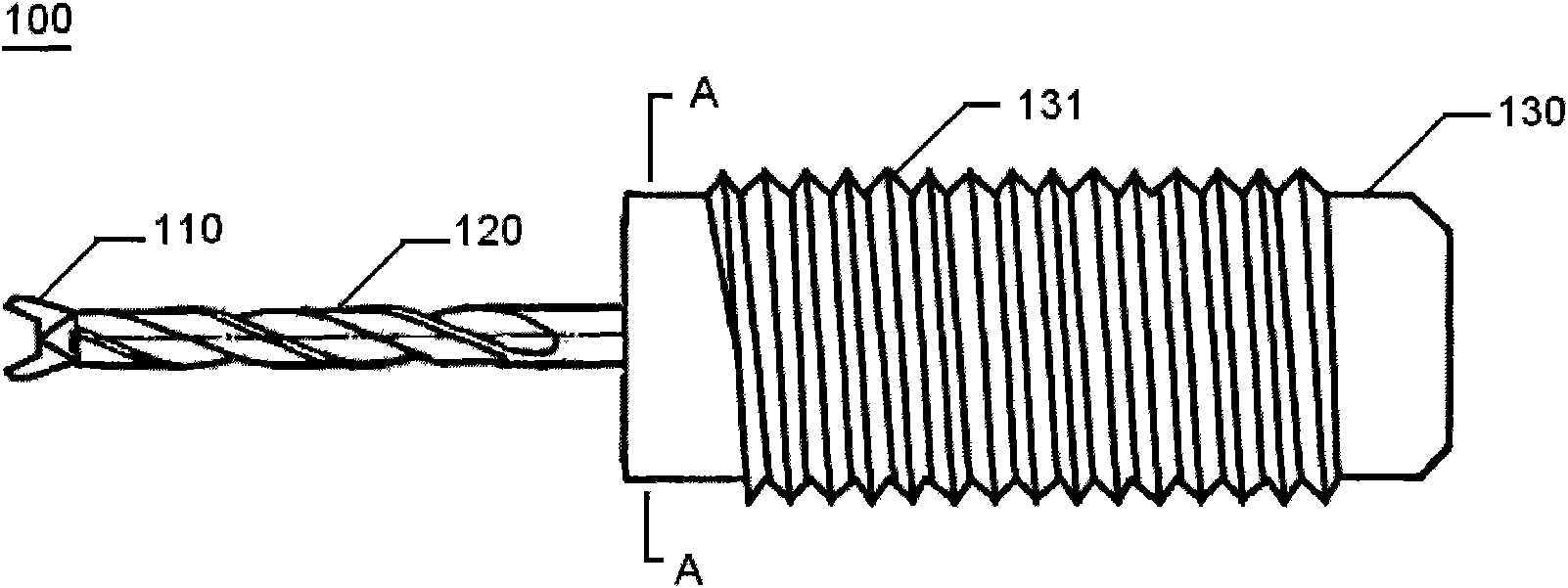
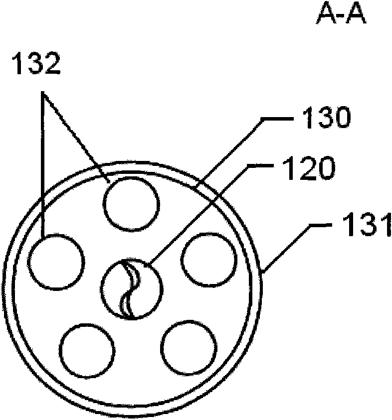
[0019] see figure 1 as shown, figure 1 It is a structural schematic diagram of the device for dredging the discharge valve of the polyurethane foam caulk tank according to the present invention. A device 100 for dredging the discharge valve of a polyurethane foam caulk tank, the device 100 at least includes a drill bit 110, a drill body 120 and a drill handle 130, the drill bit 110 is located at the front end of the drill body 120, and the drill handle 130 is arranged on At the rear end of the drill body 120, a feed groove is arranged on the drill body 120, and the feed groove is helical and distributed continuously around the entire drill body. The drill bit 110 is V-shaped, the outer surface of the drill shank 130 is provided with a thread structure 131 , and the axial direction of the drill shank 130 is provided with several through hol...


PUM


Abstract

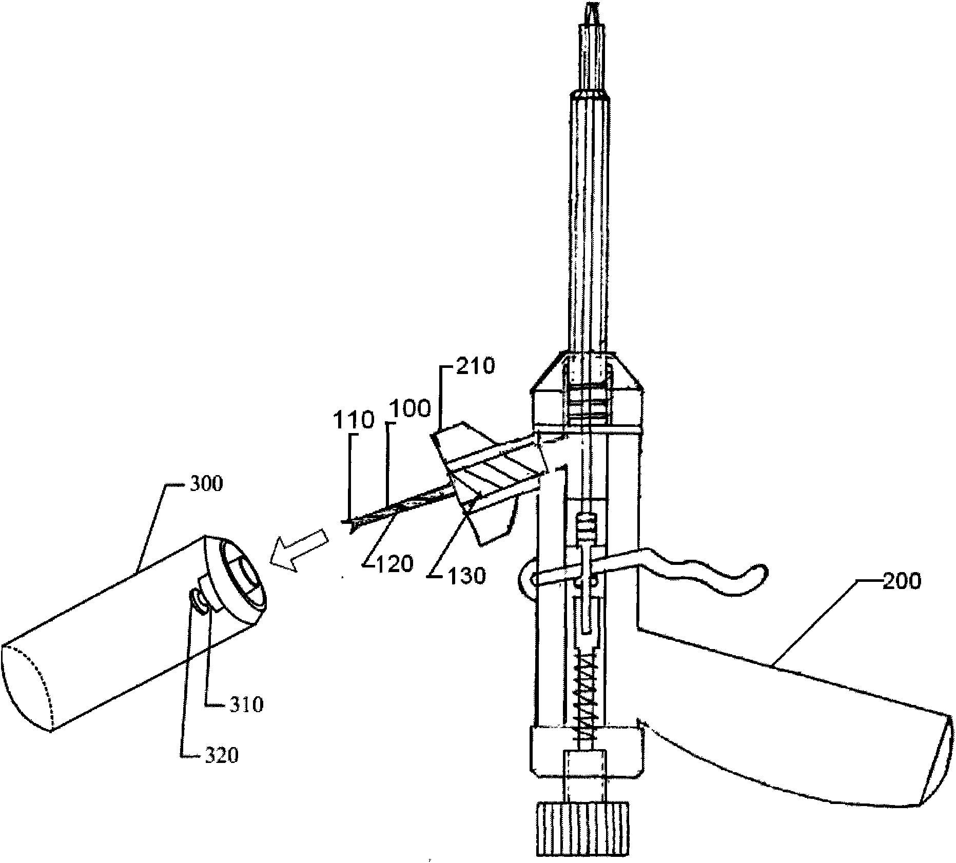
The invention discloses a device and a method for dredging a discharge valve of a polyurethane foam gap filler pot. The device at least comprises a drilling bit, a drill body and a drill handle, wherein the drill bit is positioned at the front end of the drill body; the drill handle is arranged at the back end of the drill body; the drill body is provided with feeding grooves; each of the feeding grooves is of spiral line shape and the feeding grooves are distributed on the whole drill body circularly and continuously; and the radial direction of the drill handle is provided with a plurality of through holes. The drill body is fed into the discharge valve of the polyurethane foam gap filler pot to be dredged; the drill bit is inserted into the bottom end of the discharge valve; and the drill handle is rotated to drive the bottom end of the discharge valve to twist to loose polyurethane foam plastic solidified in the discharge valve so that the solidified polyurethane foam plastic is separated from the discharge valve. The device and the method effectively solve the problem that the polyurethane foam plastic is adhered to and solidifies the discharge valve, and have the advantage of simple and convenient operation.

Description

【Technical field】 [0001] The invention relates to a device for removing solidified sealing materials, in particular to a device and method for dredging a discharge valve of a polyurethane foam caulking agent tank. 【Background technique】 [0002] At present, polyurethane foam caulking agent has been more and more used in caulking and insulation projects, thermal insulation edge finishing projects in the construction and decoration industry, and projects such as sound insulation, heat preservation, dustproof and waterproof plugging, etc., because of its convenient use, sealing Good sex occupies a wide market. Under normal circumstances, the polyurethane foam sealant is stored in the polyurethane foam sealant tank. When in use, the polyurethane foam sealant tank is equipped with a special spray gun and sprayed in the gap to be filled. After the sprayed polyurethane foam is cured, immediately Just scrape off the foam residue outside the gap. [0003] However, since polyurethan...

Claims


Application Information

Patent Timeline
IPC IPC(8): B05B15/02B05C21/00
Inventor 汤明长
Owner 上海威固化工制品有限公司
Learn More