Minitype axial flow fan with C spline bent blades

A technology of micro shafts and blades, which is used in the components of pumping devices for elastic fluids, non-variable displacement pumps, machines/engines, etc. The choice of blade height is not quantified and clear, the accurate mathematical characteristics of the bending profile are not specified, and the end loss at the blade root cannot be effectively reduced, so as to enhance the anti-stall performance, strong adaptability to changing conditions, and improve aerodynamic performance.

Inactive Publication Date: 2010-07-21
UNIV OF SHANGHAI FOR SCI & TECH
View PDF4 Cites 0 Cited by
  • Summary
  • Abstract
  • Description
  • Claims
  • Application Information

AI Technical Summary

Problems solved by technology

This kind of curved blade only limits the change of the bending angle along the blade height direction, but does not specify the exact mathematical characteristics of the specific curved line, so its manufacture has a certain degree of blindness
At the same time, since the curved blade is not bent at the blade root, it cannot effectively reduce the end loss at the blade root, so there is room for further improvement in its aerodynamic performance
[0007] For the various curved blades disclosed in the above-mentioned patents, the relationship and value of the curved profile, camber and bending angle, and the selection of the height of the curved blade have not been quantified and clarified.

Method used


Image

  • Minitype axial flow fan with C spline bent blades
  • Minitype axial flow fan with C spline bent blades
  • Minitype axial flow fan with C spline bent blades

Examples


Embodiment Construction

[0022] The present invention will be described in detail below with reference to the accompanying drawings and embodiments. However, this embodiment is not intended to limit the present invention, and all similar structures and similar changes of the present invention shall be included in the protection scope of the present invention.

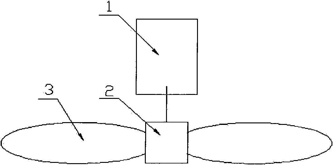
[0023] like figure 1 , 2, the micro axial flow fan with C-spline curved blades of the present invention includes a motor 1, a hub 2, and a C-spline curved blade 3.

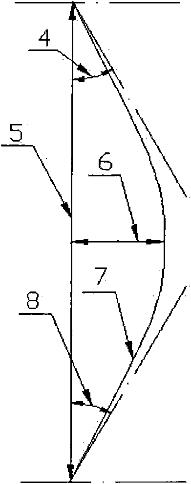
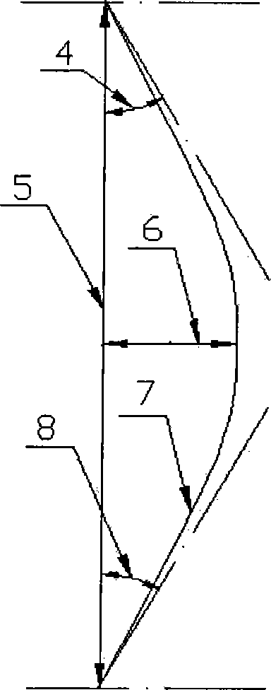
[0024] The C-spline curved blades 3 are installed on the hub 2 at equal intervals. The hub 2 is connected to the motor 1 through the rotating shaft. The curved line 7 of the C-spline curved blade 3 is formed by smooth connection of two C-spline curves. And it satisfies the following mathematical analytic relations:

[0025] x = 3 tan α ...


PUM


Abstract

The invention relates to a minitype axial flow fan with C spline bent blades. The minitype axial flow fan comprises a motor, a hub and C spline bent blades, wherein the C spline bent blades are arranged on the hub at intervals along the circumferential direction; the hub is connected with the motor through a rotating shaft; a bent line of each C spline bent blade consists of two C spline curves in smooth connection; a bent angle of the upper end wall of the bent blade is equal to that of the lower end wall and is between 10 and 40 degrees; the curvature of the bent blade is 1/6 to 1/3 times of a tangential value of the bent angle of the corresponding end wall; the outside diameter of the bent blade is no more than 120 mm; and the height of the bent blade is 0.3 times of the corresponding outside diameter. The minitype axial flow fan has the advantages that: by reasonably controlling the bending form of the blade, the loss of the end part of a blade path is reduced, the separation of a boundary layer of the surface of the blade is inhibited, and the pneumatic efficiency of the fan is improved so as to reduce the pneumatic noise. Through experiments, the minitype axial flow fan of the invention has low noise, small flowing loss and high efficiency and can be effectively applied to ventilation and radiation of various electronic devices.

Description

technical field [0001] The invention relates to a miniature axial flow fan used for heat dissipation and ventilation of electronic equipment, in particular to a miniature axial flow fan formed by installing a C-spline curved blade with a specified shape, a specified bending angle, a specified curvature and a specified blade height on a hub. Axial fan. Background technique [0002] Axial fans with impeller diameters below 120mm are called micro-axial fans. They are widely used in the fields of electronics industry, automation technology, military technology, aerospace and household appliances, especially in electronic equipment such as computers. It is a cooling device for important working parts. [0003] At present, with the continuous improvement of the performance of electronic equipment such as computers, the workload of its core components is increasing day by day, and the heat generation is increasing. The heat dissipation problem of these electronic components has b...

Claims


Application Information

Patent Timeline
Patent Type & Authority Applications(China)
IPC IPC(8): F04D29/38
Inventor 王企鲲
Owner UNIV OF SHANGHAI FOR SCI & TECH
Why Eureka
Try Eureka