
Displacement adjusting system and method for combustion gas turbine rotor

A gas turbine and displacement adjustment technology, which is applied to mechanical equipment, engine components, machines/engines, etc., can solve problems such as air leakage loss of the unit, achieve the effect of increasing the output power of the gas turbine, reducing the end loss, and optimizing the efficiency of the gas turbine

Pending Publication Date: 2017-12-01
SHANGHAI ELECTRIC GAS TURBINE CO LTD
View PDF0 Cites 1 Cited by
  • Summary
  • Abstract
  • Description
  • Claims
  • Application Information

AI Technical Summary

Problems solved by technology

[0004] In view of the shortcomings of the prior art described above, the purpose of the present invention is to provide a gas turbine rotor displacement adjustment system and adjustment method for solving the problem of air leakage loss inside the unit in the prior art

Method used


Image

  • Displacement adjusting system and method for combustion gas turbine rotor
  • Displacement adjusting system and method for combustion gas turbine rotor
  • Displacement adjusting system and method for combustion gas turbine rotor

Examples


Embodiment Construction

[0056] The implementation of the present invention will be illustrated by specific specific examples below, and those skilled in the art can easily understand other advantages and effects of the present invention from the contents disclosed in this specification.

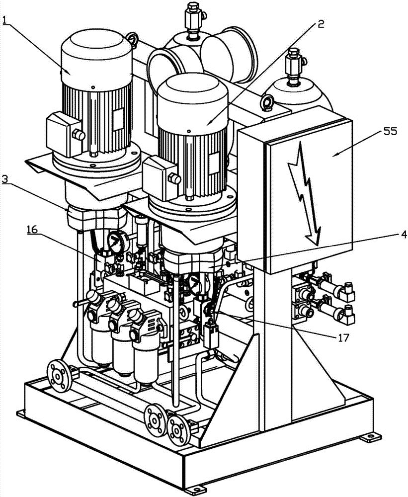
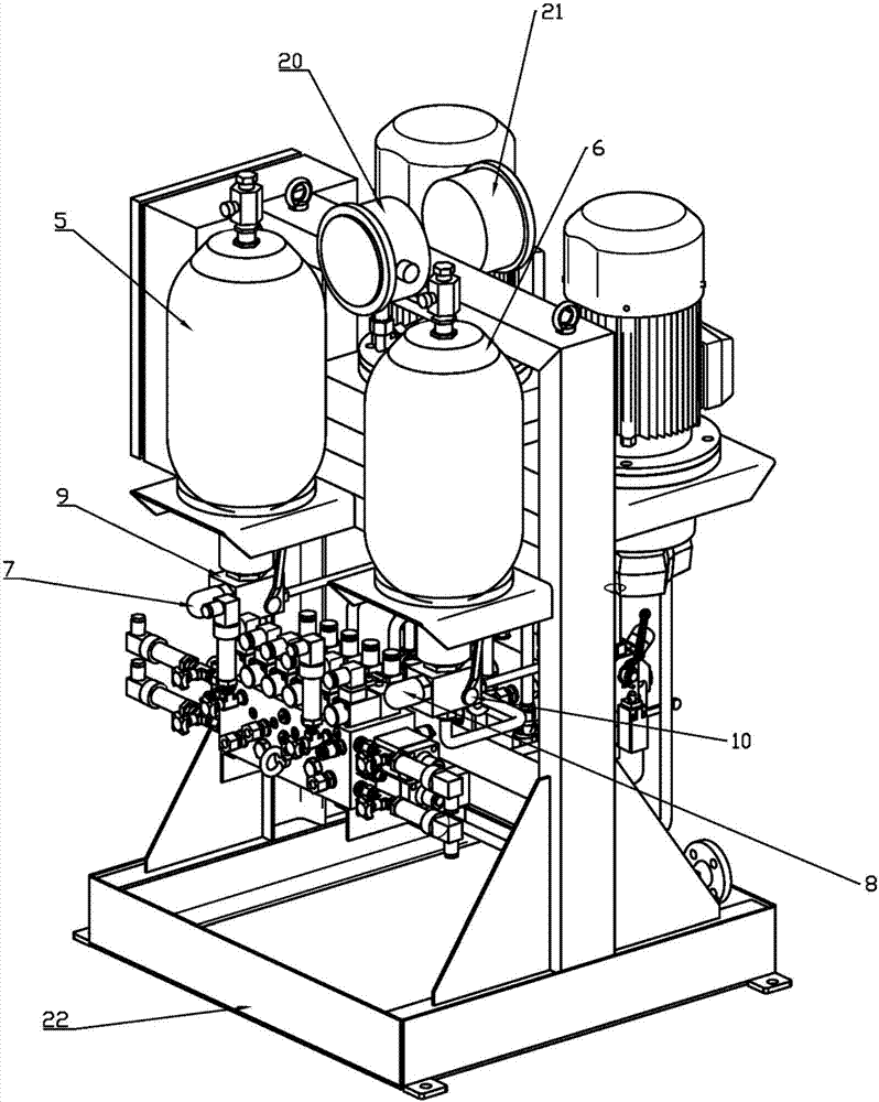
[0057] see Figure 1 to Figure 8 . It should be noted that the structures, proportions, sizes, etc. shown in the drawings attached to this specification are only used to match the content disclosed in the specification, for those who are familiar with this technology to understand and read, and are not used to limit the implementation of the present invention. Limiting conditions, so there is no technical substantive meaning, any modification of structure, change of proportional relationship or adjustment of size, without affecting the effect and purpose of the present invention, should still fall within the scope of the present invention. within the scope covered by the disclosed technical content. At the same ti...


PUM


Abstract

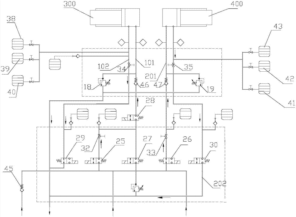
The invention provides a displacement adjusting system and method for a combustion gas turbine rotor. The displacement adjusting system comprises a booster pump connected with an oil supply pipeline, an energy accumulator connected with the booster pump and two ways of hydraulic pipelines connected with the energy accumulator. The first hydraulic pipeline communicates with a main push cavity located in the gas compressor side in a combustion gas turbine, and the second hydraulic pipeline communicates with an auxiliary push cavity located on the gas compressor side in the combustion gas turbine. The main push cavity is connected with a first oil return pipe, and the auxiliary push cavity is connected with a second oil return pipe. Each of the first hydraulic pipeline and the second hydraulic pipeline is provided at least one turn-off electromagnetic valve, and each of the first oil return pipe and the second oil return pipe is provided with an oil return electromagnetic valve. The booster pump, all the turn-off electromagnetic valves and all the oil return electromagnetic valves are connected with a control system. By means of the displacement adjusting system and method, the efficiency of the gas turbine is optimized by controlling the axial displacement of the combustion gas turbine rotor.

Description

technical field [0001] The invention relates to the technical field of gas turbines, in particular to a gas turbine rotor displacement adjustment system and an adjustment method. Background technique [0002] Modern gas turbines are developing towards greater power and higher efficiency. After a new generation of gas turbines is finalized, they will continue to improve, and continue to use new technologies and materials to improve unit performance, increase output and improve efficiency. The flow design of modern gas turbines applies the most advanced design idea of ​​full three-dimensional viscous gas dynamics. The efficiency is close to the extreme, and the room for further improvement is limited. Therefore, we have to seek improvement of unit performance from other aspects. The gas turbine is a high-speed rotating machine. From the perspective of safety, there will be a certain gap between the rotor part and the stator part. The gap is close to the extreme under the curr...

Claims


Application Information

Patent Timeline
IPC IPC(8): F01D11/20
CPCF01D11/20
Inventor 唐健陈浩张栋芳杨瑞琪严晶郭强
Owner SHANGHAI ELECTRIC GAS TURBINE CO LTD
Learn More