Blade tip clearance control

Inactive Publication Date: 2006-08-29
SIEMENS ENERGY INC
View PDF18 Cites 26 Cited by
  • Summary
  • Abstract
  • Description
  • Claims
  • Application Information

AI Technical Summary

Benefits of technology

[0004]Thus, one object according to aspects of the present invention is to provide a method for actively controlling blade tip clearances. Another object according to aspects of the invention is to provide a turbine engine assembly configured to actively manage blade tip clearances under various operating conditions. Still another object according to aspects of the invention is to reduce blade tip clearances and the losses occurring over the blade tips at substantially steady state or full power operation of the turbine so as to improve engine performance. A further object according to aspects of the invention is to increase blade tip clearances during substantially transient engine operation such as at startup. These and other objects according to aspects of the present invention are addressed below.
[0006]Air exiting the compressor section at a compressor exit temperature is provided. In one embodiment, the compressor exit temperature can be about 450 degrees Celsius. At least a portion of the air exiting the compressor section is routed to the rotor and discs of the turbine section without substantially reducing the temperature of the air portion from the compressor exit temperature as it is presented to the rotor and discs. As a result, blade clearances, defined between the tips of the blades and the neighboring ring segments, are minimized due to the thermal expansion of the rotor and discs.

Problems solved by technology

One of the major flow path losses is due to the leakage of hot combustion gases across the tips of the turbine blades.
In particular, the leakage occurs across a space between the tips of the rotating turbine blades and the surrounding stationary structure such as the ring segments.
Blade tip clearances cannot be eliminated because, during transient conditions such as during engine startup or part load operation, the rotating parts (blades, rotor, and discs) and stationary parts (outer casing, blade rings, and ring segments) thermally expand at different rates.
As a result, blade tip clearances can actually decrease during engine startup until steady state operation is achieved at which point the clearances can increase, thereby reducing the efficiency of the engine.

Method used


Image

  • Blade tip clearance control
  • Blade tip clearance control
  • Blade tip clearance control

Examples


Embodiment Construction

[0016]Aspects of the present invention generally relate to improving the efficiency of turbine engines. More particularly, aspects of the invention relate to the active management of blade tip clearances at various instances during the operation of a turbine engine. Aspects of the invention are described in connection with turbine engine assemblies and methods of operating such turbine engines.

[0017]Embodiments according to aspects of the invention are shown in FIGS. 1–2, but the present invention is not limited to the illustrated structure or application. Further, the following detailed description is intended only as exemplary.

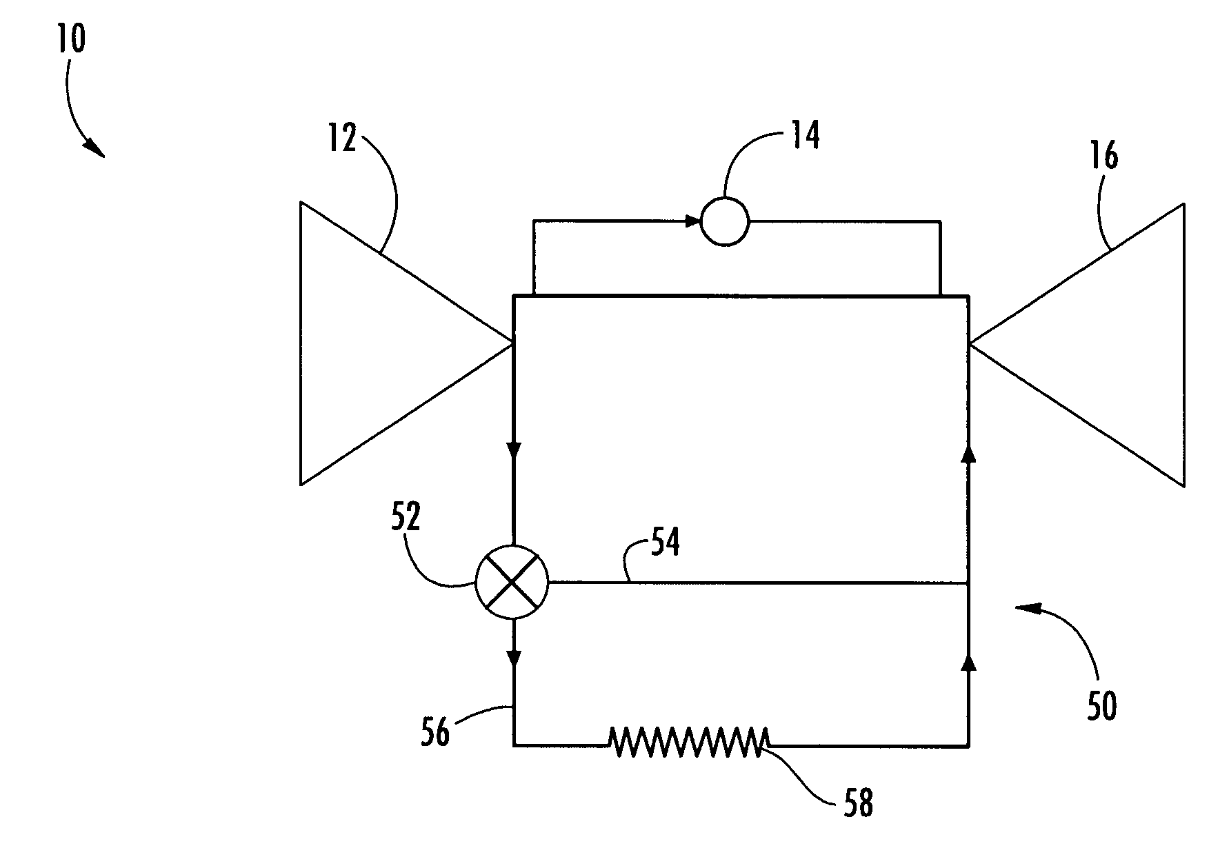
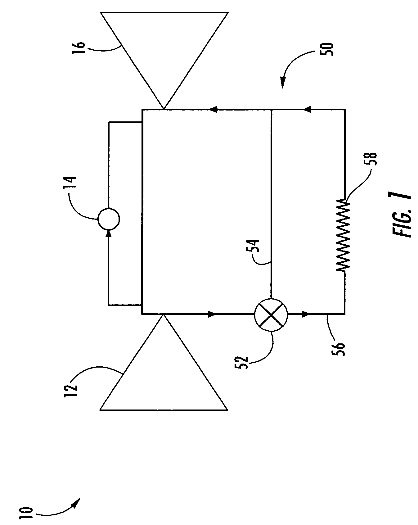
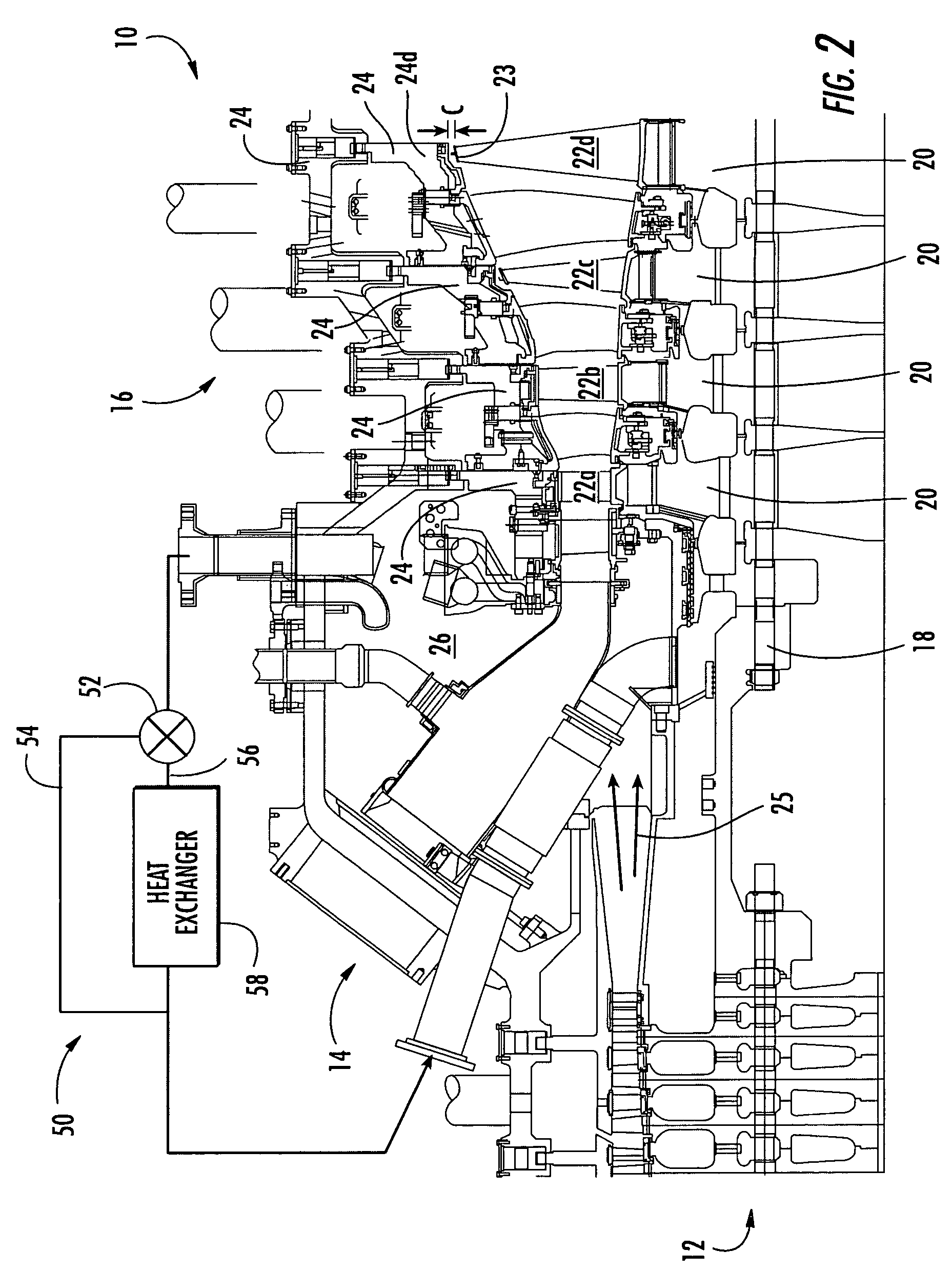
[0018]Aspects of the invention can be applied to a variety of turbine engine systems. In basic form, a turbine engine 10 can generally include a compressor section 12, a combustor section 14 and a turbine section 16 (FIG. 1). Each of these sections can have a variety of components and configurations. As shown in FIG. 2, the turbine section 16 can include a r...


PUM


Abstract

Aspects of the invention relate to methods and assemblies for improving the efficiency of a turbine engine through active management of blade tip clearances. In some designs, a portion of compressor exit air is routed to the rotor and discs of the turbine section. Aspects of the invention relate to treating the compressor exit air in light of the operating conditions of the engine. For instance, under base load or substantially steady state operation, a portion of compressor exit air can be routed to the rotor and discs without reducing the temperature of the compressor exit air. In such case, blade tip clearances will reduce, allowing for improved engine efficiency. Under part load or substantially transient operating conditions, a portion of compressor exit air can be cooled before it is supplied to the rotor and discs. As a result, the blade tip clearances increase, minimizing concerns of blade tip rubbing. Routing of the compressor exit air for cooling and bypass can be controlled by a valve.

Description

FIELD OF THE INVENTION[0001]The invention relates in general to turbine engines and, more particularly, to an engine assembly and an associated method for optimizing engine efficiency by reducing blade tip clearances.BACKGROUND OF THE INVENTION[0002]Turbine engines commonly operate at efficiencies ranging from about 30% to about 40%. The operational efficiency is less than the theoretical maximum because of losses that occur in the flow path. One of the major flow path losses is due to the leakage of hot combustion gases across the tips of the turbine blades. In particular, the leakage occurs across a space between the tips of the rotating turbine blades and the surrounding stationary structure such as the ring segments. This spacing is often referred to as the blade tip clearance.[0003]Blade tip clearances cannot be eliminated because, during transient conditions such as during engine startup or part load operation, the rotating parts (blades, rotor, and discs) and stationary parts...

Claims


Application Information

Patent Timeline
IPC IPC(8): F02C7/18F01D5/08F01D11/24
CPCF01D5/081F01D11/24F01D5/085
Inventor LITTLE, DAVID A.MCQUIGGAN, GERRY
Owner SIEMENS ENERGY INC
Why Eureka
Try Eureka