Integrated multidirectional distribution valve for liquid delivery

A technology for distributing valves and liquids, applied in the field of multi-directional conversion devices for fluid conveying pipelines, can solve the problems that the residual medium in the pipeline cannot be cleaned online, the conveying medium and equipment can be polluted, and the manufacturing process of the ball valve is complicated, etc. Guarantee stability and reliability, and improve the effect of product quality

Inactive Publication Date: 2010-07-21
TIANJIN UNIV OF SCI & TECH
View PDF5 Cites 5 Cited by
  • Summary
  • Abstract
  • Description
  • Claims
  • Application Information

AI Technical Summary

Problems solved by technology

At present, the more common devices are two-way or three-way ball valves. Although this type of valve can realize the selection and conversion of different conveying directions of the pipeline, in the case of many pipeline branches, the two-way or three-way can no longer meet the needs. , and limited to the special structure of the ball valve spool, the manufacturing process of the ball valve with more than four channels is more complicated, and it is difficult to ensure the sealing of the valve body under more channels
In addition, the conveying direction can also be controlled by adding a one-way valve to the general branch pipeline, which can realize simple control of the direction, but in the production process that requires precision and cleanliness, the residual medium in the pipeline cannot be cleaned online, which will inevitably pollute Conveying media and equipment, thereby affecting product quality

Method used


Image

  • Integrated multidirectional distribution valve for liquid delivery
  • Integrated multidirectional distribution valve for liquid delivery
  • Integrated multidirectional distribution valve for liquid delivery

Examples


Embodiment Construction

[0022] The present invention will be further described in detail below through specific embodiments in conjunction with the accompanying drawings.

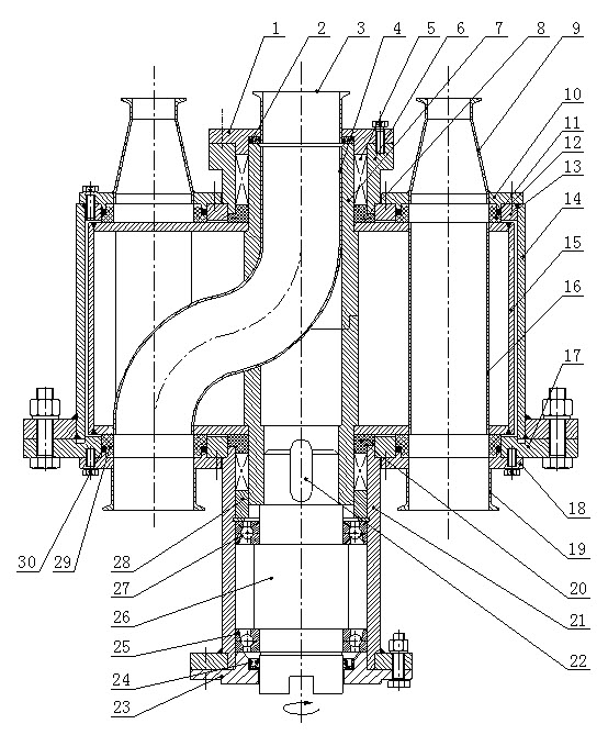
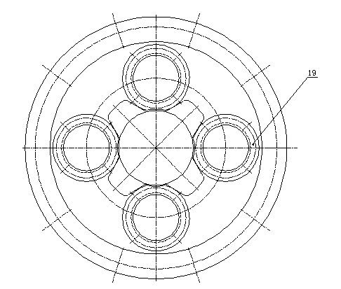
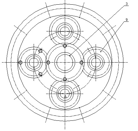
[0023] An integrated liquid delivery multi-directional distributing valve includes a valve body and a valve core. The innovation of this multi-directional distributing valve is: the valve body is composed of a housing 14 and a main end cover fixedly mounted on the lower part, the upper end surface 13 of the upper part of the housing is integrally made with the housing or welded on the upper end of the housing, the main end Cover 17 is fixed on the lower end of the cylindrical housing by bolts. A main liquid inlet 3 is fixed in the middle of the upper end surface, and the main liquid inlet is fixed in the shaft sleeve 6 fixed on the upper end surface of the valve body through the central flange 1 . 3-8 liquid outlets 19 are uniformly distributed in a ring on the main end cover, and 4 liquid outlets are provided in this embodiment....


PUM


Abstract

The invention relates to an integrated multidirectional distribution valve for liquid delivery, comprising a valve body and a drum-shaped valve plug, wherein the valve body comprises a casing and a main end cover fixedly arranged on the lower part of the casing; a main liquid inlet is fixedly arranged in the middle of the upper end face of the casing; a plurality of liquid outlets are annularly and uniformly distributed and fixedly arranged on the main end cover on the lower part; the drum-shaped valve plug is coaxially rotatably arranged in the valve body and comprises rotating boxes, hollow mandrels and S-shaped liquid pipes; transmission boxes are coaxially and fixedly arranged outside the main end cover of the valve body; a drive shaft is coaxially arranged in the transmission boxes and is coaxially linked with the lower ends of the hollow mandrels of the drum-shaped valve plug. The multidirectional distribution valve is compact in structure and scientific and reasonable in design and realizes multichannel switching and butting of the pipes by utilizing the electrodynamic drum-shaped valve plug, thus ensuring the liquid media to be accurately and selectively delivered to the specified directions without residues and leakage in the device, and the multidirectional distribution valve has the advantages of simple operation, steady operation, good leak tightness, etc.

Description

technical field [0001] The invention relates to a multi-directional switching device for fluid delivery pipelines, in particular to an integrated multi-directional distribution valve for liquid delivery. Background technique [0002] Fluid is an important medium in light industry and chemical production. In various production processes, it is often necessary to carry out selective distribution of fluid, that is, to transport the fluid medium from the same pipeline to different directions for use, or to transport the fluid medium from different pipelines to the same container middle. At present, the more common devices are two-way or three-way ball valves. Although this type of valve can realize the selection and conversion of different conveying directions of the pipeline, in the case of many pipeline branches, two-way or three-way can no longer meet the needs. , and limited to the special structure of the ball valve spool, the manufacturing process of the ball valve with ...

Claims


Application Information

Patent Timeline
Patent Type & Authority Applications(China)
IPC IPC(8): F16K11/06F16K31/04F16K31/44F16K31/53B08B3/04
Inventor 卢晓江何迎春赖维
Owner TIANJIN UNIV OF SCI & TECH
Why Eureka
Try Eureka