
Arrangement for screw locking electric connecting terminals

A locking device and electrical wiring technology, applied in conductive connections, hand tools suitable for fasteners, nuts, etc., can solve the problems of narrow production tolerance range, narrow structure size determination range, etc., achieve large tolerance range, easy installation , The effect of simple part demoulding operation

Inactive Publication Date: 2010-07-21
PHOENIX CONTACT GMBH & CO KG
View PDF2 Cites 7 Cited by
  • Summary
  • Abstract
  • Description
  • Claims
  • Application Information

AI Technical Summary

Problems solved by technology

[0005] The disadvantage of this known screw locking device for electrical terminals in the prior art is that, in this known screw locking device, although falling off is avoided, a very narrow range of structural dimensions is required, and Also limited to a narrow range of manufacturing tolerances

Method used


Image

  • Arrangement for screw locking electric connecting terminals
  • Arrangement for screw locking electric connecting terminals
  • Arrangement for screw locking electric connecting terminals

Examples


Embodiment Construction

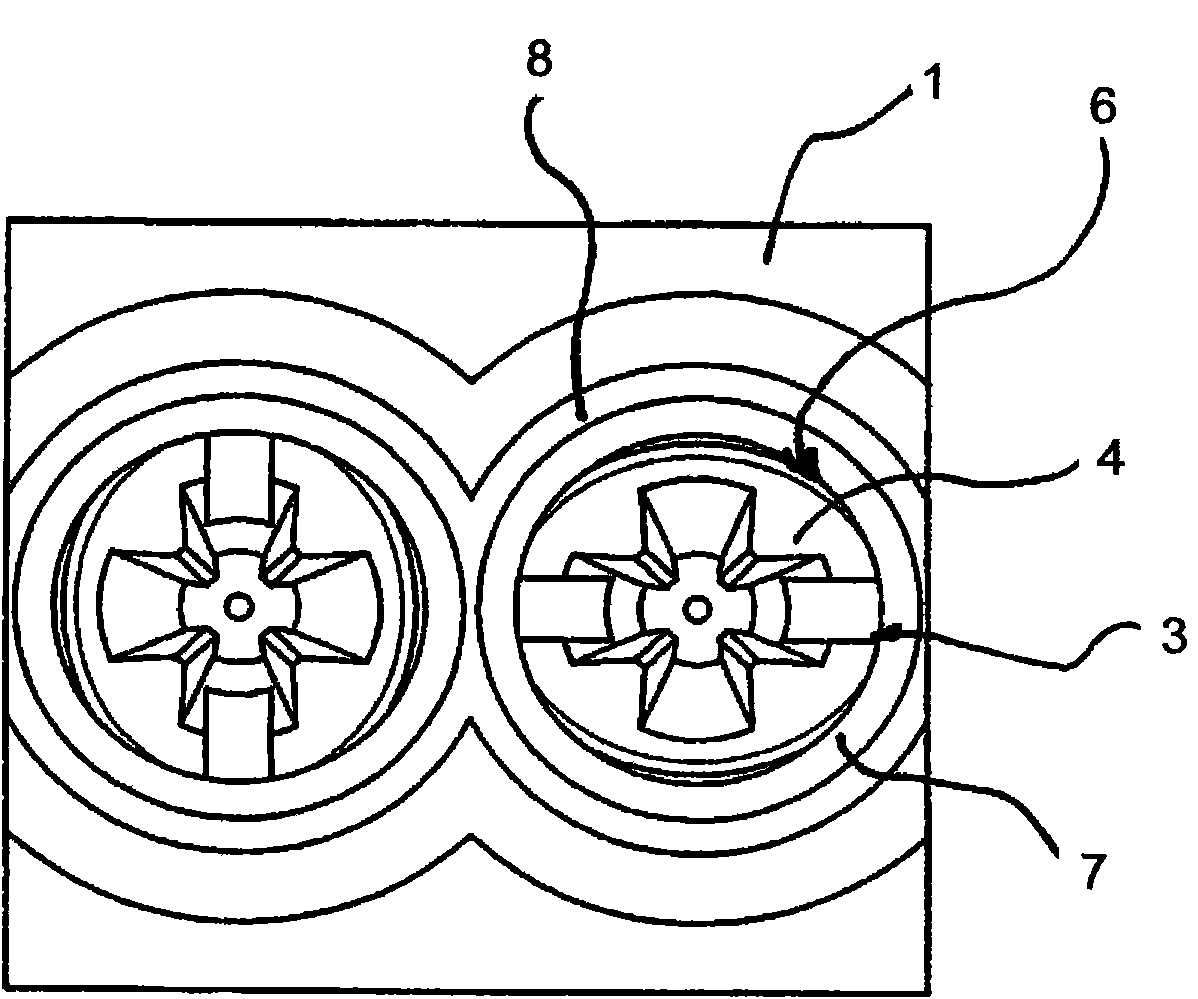
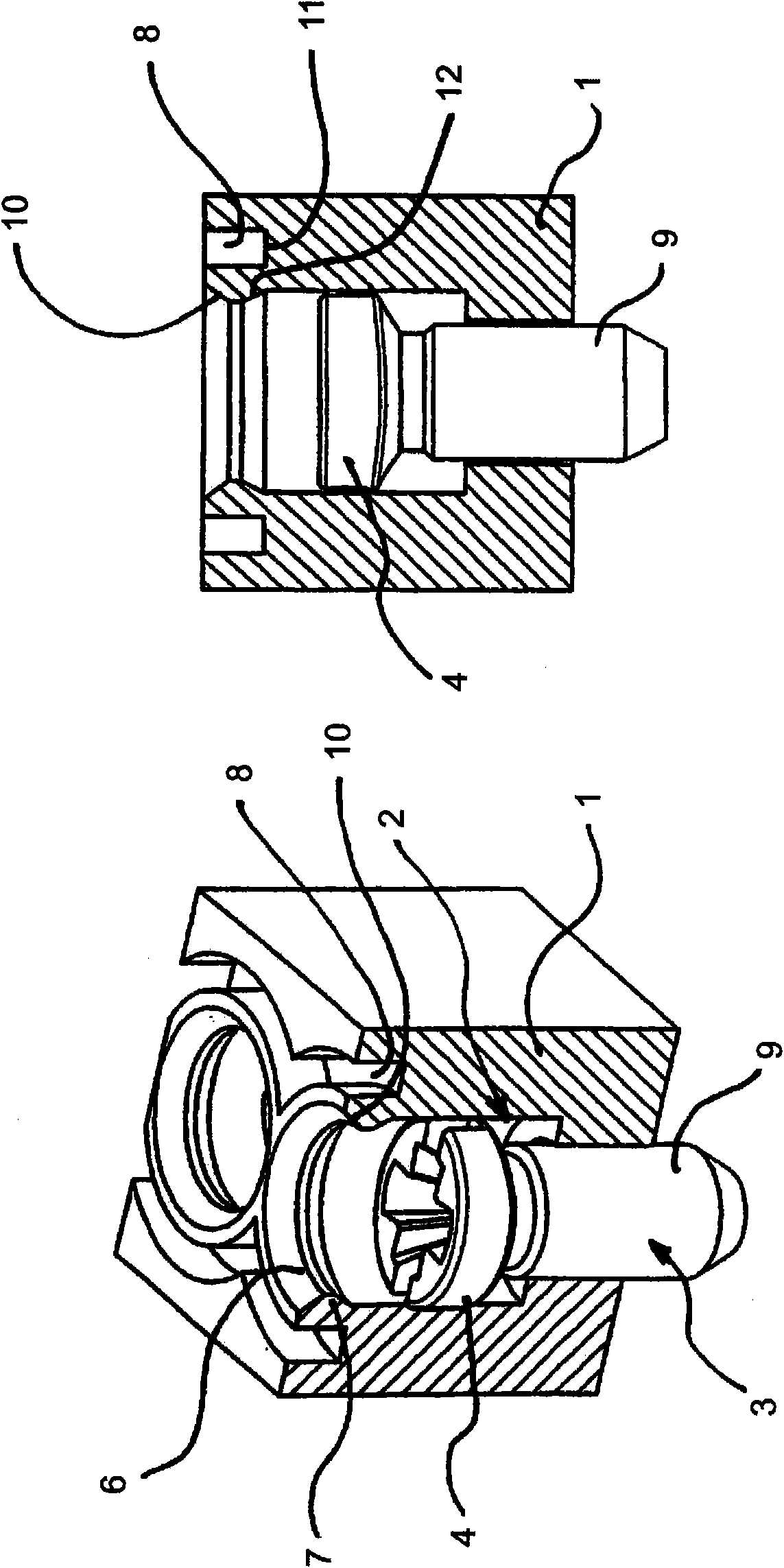
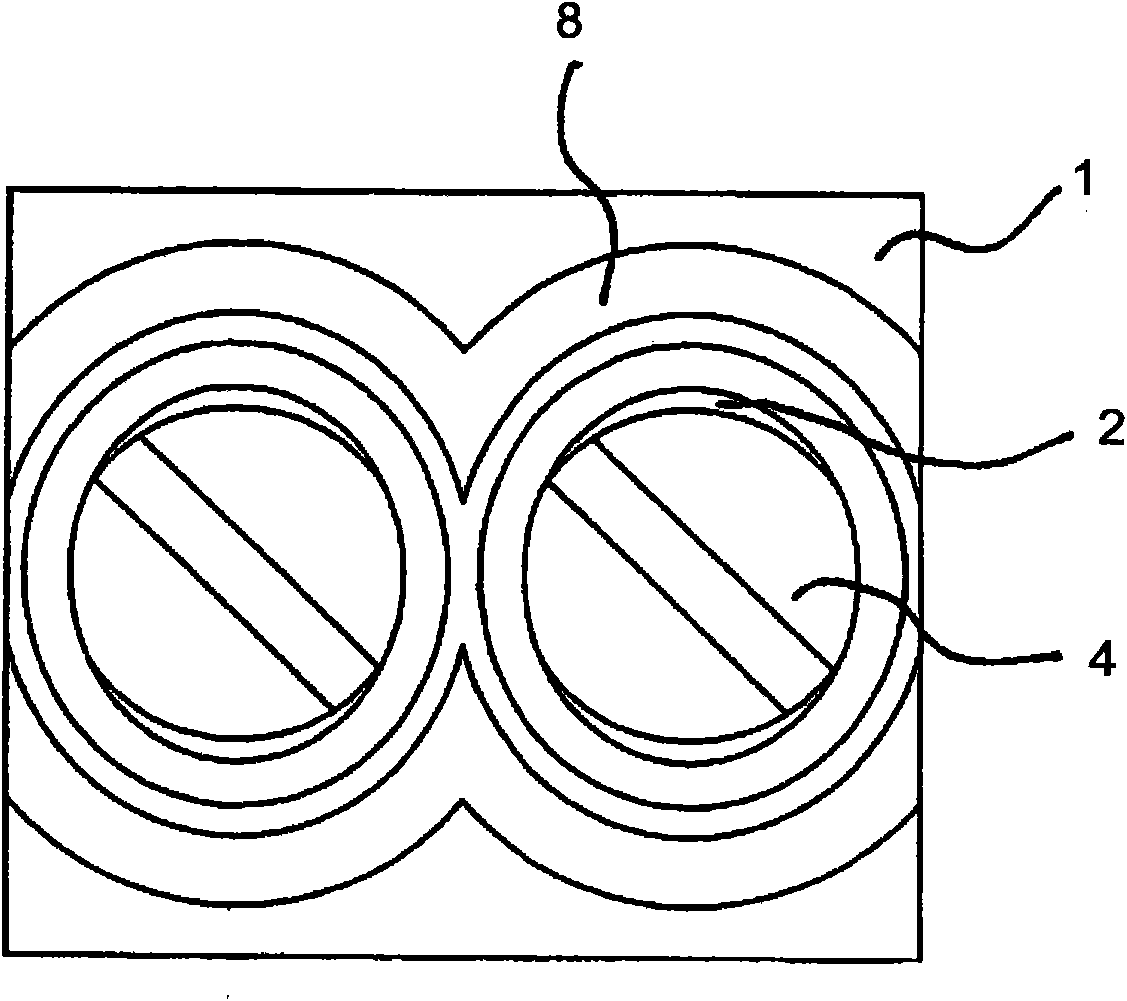
[0020] Figure 1 to Figure 4 The screw locks for the terminal blocks are shown respectively. Therein, the device comprises a body or shell-like part 1 made of an insulating deformable material, for example of plastic material. Formed in the body or shell-like part 1 is a vertically extending well 2, into which a screw 3 can be sunkly inserted, comprising a screw head 4, as in particular figure 2 with Figure 4 shown in . In order to ensure the automatic locking of the screw 3 or make the screw 3 inseparable, according to figure 1 with figure 2 In a first embodiment of the present invention, a striped structure 6 may be provided in the area of ​​the well wall 5 . Wherein, the stripe structure 6 is designed in such a way that the stripe structure 6 can be elastically deformed when the screw head 4 passes through, that is, during the screw-in process. That is to say, when the screw head 4 sinks into the shaft structure 2 , the stripe structure 6 is pressed back, wherein t...


PUM


Abstract

The invention relates to an arrangement for screw locking electric connecting terminals, comprising a body or a housing-like element (1) made of insulating, deformable material, preferably a plastic material, in which a perpendicularly extending duct (2) is integrally formed, into which a screw (3) including the head (4) thereof can be screwed in a sunken way. A profile (6) is provided in the region of the duct wall (5) for securing the sunken screw (3), said profile being elastically deformable when screwing in the screw (3) and while passing over the head (4), wherein the profile (6) is deformed back toward the inside of the duct for securing the screw (3) after passing over the head (4). According to the invention, the duct wall (5) is provided with a groove (8) integrally formed in the material, wherein the screw (3) or the duct (2) has a noncircular shape.

Description

technical field [0001] The invention relates to a screw locking device for an electrical terminal, said screw locking device comprising a body or shell-like part made of an insulating deformable material, preferably a plastic material In this way, a substantially vertically extending well-like structure is formed in the body or the shell-like part, and a screw can be sunkly screwed into the well-like structure, and the screw includes a screw head, wherein, in order to ensure that the sinking In order to lock the head screw, a striped structure is provided on the area of ​​the well wall, and the striped structure is elastically deformed during the screwing-in process of the screw and when the screw head passes through, wherein, for locking The striated structure of the screw returns to the shape inside the original well-like structure again after the screw head has passed through. Background technique [0002] Such screw locks for preventing the screws from locking themselve...

Claims


Application Information

Patent Timeline
Patent Type & Authority Applications(China)
IPC IPC(8): H01R4/30F16B41/00
CPCH01R4/301Y10S411/999F16B41/002Y10T29/53209
Inventor 于尔根·法伊-霍曼
Owner PHOENIX CONTACT GMBH & CO KG
Learn More