Process for replacing hoisting ropes

A steel wire rope and process technology, applied in the field of lifting steel wire rope replacement technology, can solve the problems of long construction period, poor construction safety, endangering the safety of construction personnel, etc., and achieve the effect of saving time and labor, saving construction time and reducing labor intensity

Active Publication Date: 2010-07-28
山东煤安矿山提升设备安装有限公司
View PDF4 Cites 24 Cited by
  • Summary
  • Abstract
  • Description
  • Claims
  • Application Information

AI Technical Summary

Problems solved by technology

[0002] The existing shaft shaft hoisting wire rope replacement process has the following deficiencies: 1. In the existing replacement process, two-rope boards and six-rope boards are used; It is cumbersome and complicated, and the number of boards used is large
2. In the existing replacement process, not only the construction at the upper wellhead, but also the construction at the lower wellhead is required. The construction safety is poor, and the construction efficiency is low and the construction period is long
3. In the existing process, the new steel wire rope is attached to the old steel wire rope from the upper wellhead to the lower wellhead. The new and old rope ends need to be removed at the lower wellhead and connected to the cage, because the new and old rope ends have certain rotations. In the construction process, it is easy to have twisting accidents between steel wire ropes. Once the phenomenon of steel wire rope twisting occurs, it is quite troublesome to deal with. It not only takes a long time and delays the construction period, but also is very dangerous and endangers the safety of construction personnel.
This old process is less safe, prone to accidents, labor efficiency is not high, the construction period is longer, and the project cost is higher

Method used


Image

  • Process for replacing hoisting ropes
  • Process for replacing hoisting ropes
  • Process for replacing hoisting ropes

Examples


Embodiment Construction

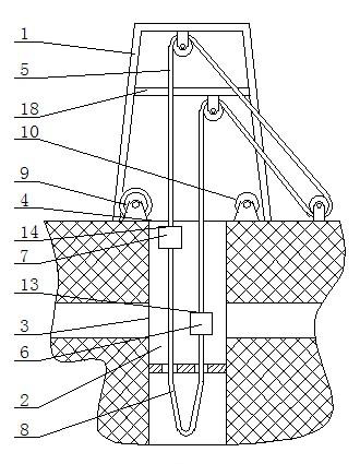
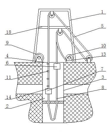
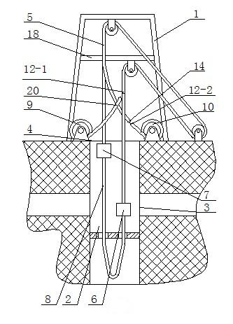
[0017] Usually the first cage 6 and the second cage 7 are jointly suspended by four old steel wire ropes 5 side by side. In order to quickly replace the old steel wire ropes 5 on the premise of ensuring safety, the outermost two old steel wire ropes 5 can be replaced at the same time. Replace the two in the middle again, or replace the two old steel ropes 5 in the middle and then replace the two old steel ropes 5 in the outermost side. Take the well shaft 2 with four old steel ropes 5 in total as an example. Figures 1 to 6 Specifically describe the hoisting wire rope replacement process steps of the present invention as follows:

[0018] Such as figure 1 As shown, 1. first place two new rope cars 9 and two old rope cars 10 near the upper wellhead 4 of the well shaft 2, and start the winch 15 to raise the second cage 7 to the upper wellhead 4, and the first cage 6 is lowered to the upper wellhead 4. The lower wellhead 3 of the shaft 2 completes the positioning work;

[0019]...


PUM


Abstract

The invention discloses a process for replacing hoisting ropes, which comprises the steps of: 1, arranging new and old rope hoists at an upper wellhead, and lifting a second cage to the upper wellhead; 2, lowering the second cage, and arranging a pair of long boards on an old rope on the same side of the second cage at intervals of 50 meters; 3, separating the old rope from a first cage and connecting the old rope with an old rope take-up hoist; 4, when the second cage is lifted to the upper wellhead, taking up the old rope by the old rope take-up hoist, dismounting the long boards in the step 2, and breaking the old rope; 5, connecting the rope end of a new rope with an upper breaking point, and connecting a second end of the old rope with a lower breaking point; 6, driving the new rope by the old rope to wind two hoisting sheaves and a winch sequentially, breaking the new rope and the upper breaking point, and connecting the new rope with the second cage; and 7, driving the new rope to descend by the second cage, applying pull force to the new rope at intervals of 50 meters, arranging the long boards on the new rope and a to-be-replaced old rope, removing the pull force, breaking the new rope, and connecting the new rope with the first cage.

Description

technical field [0001] The invention relates to a hoisting wire rope replacement process. Background technique [0002] The existing shaft shaft hoisting wire rope replacement process has the following deficiencies: 1. In the existing replacement process, two-rope boards and six-rope boards are used; It is cumbersome and complicated, and the use of boards is large. 2. In the existing replacement process, not only construction at the upper wellhead, but also construction at the lower wellhead is required. The construction safety is poor, and the construction efficiency is low and the construction period is long. 3. In the existing process, the new steel wire rope is attached to the old steel wire rope from the upper wellhead to the lower wellhead. The new and old rope ends need to be removed at the lower wellhead and connected to the cage, because the new and old rope ends have certain rotations. In the construction process, it is easy to have twisting accidents between ste...

Claims


Application Information

Patent Timeline
Patent Type & Authority Applications(China)
IPC IPC(8): B66B19/02
Inventor 单保民
Owner 山东煤安矿山提升设备安装有限公司
Why Eureka
Try Eureka