Vertical top pull down hydraulic pumping unit

A pumping unit, hydraulic technology, applied in the direction of liquid variable volume machinery, mechanical equipment, machine/engine, etc., can solve the problems of short service life, high maintenance cost, inconvenient use, etc., and achieve long service life and low maintenance cost. , easy to use effect

Active Publication Date: 2015-09-23
合立智能装备有限责任公司 +1
View PDF5 Cites 0 Cited by
  • Summary
  • Abstract
  • Description
  • Claims
  • Application Information

AI Technical Summary

Problems solved by technology

[0003] The present invention provides a vertical up-and-down hydraulic pumping unit, which overcomes the deficiencies of the prior art and solves the problems of complex structure, short service life, inconvenient use, and high maintenance cost in the prior art. It has a reasonable structure And compact, long service life, easy to use, good installation, low energy consumption, low maintenance costs and other advantages

Method used


Image

  • Vertical top pull down hydraulic pumping unit
  • Vertical top pull down hydraulic pumping unit
  • Vertical top pull down hydraulic pumping unit

Examples


Embodiment 3

[0026] Embodiment 3: as attached Figures 7 to 8 As shown, the difference from the above-mentioned vertical top-down hydraulic pumping unit is: as attached Figure 7 As shown, the base of the frame 15 of Embodiment 3 is located on the ground, which is convenient for installation.

Embodiment 4

[0027] Embodiment 4: as attached Figures 7 to 8 As shown, the difference with embodiment 3 is: as attached Figure 8 As shown, the hydraulic device of embodiment 4 and its corresponding frame 15 part have heat preservation chamber 20, and hydraulic device is positioned at heat preservation chamber 20, and the base of the frame 15 of embodiment 4 can be positioned on the ground, preferably embodiment 4 The hydraulic device and the heat preservation chamber 20 of the corresponding rack 15 part are placed in a relatively constant temperature layer below the ground, which becomes a basement type when in use, because too high or too low ambient temperature is not conducive to the hydraulic device for a long time. Normal work, so that the working environment of the hydraulic device is in a relatively stable state, which is conducive to reducing the failure of the hydraulic device, thereby prolonging the service life of the hydraulic device, reducing maintenance costs, and utilizing...

Embodiment 1

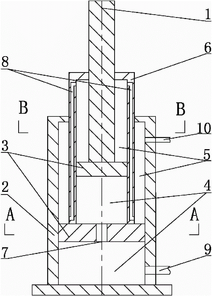
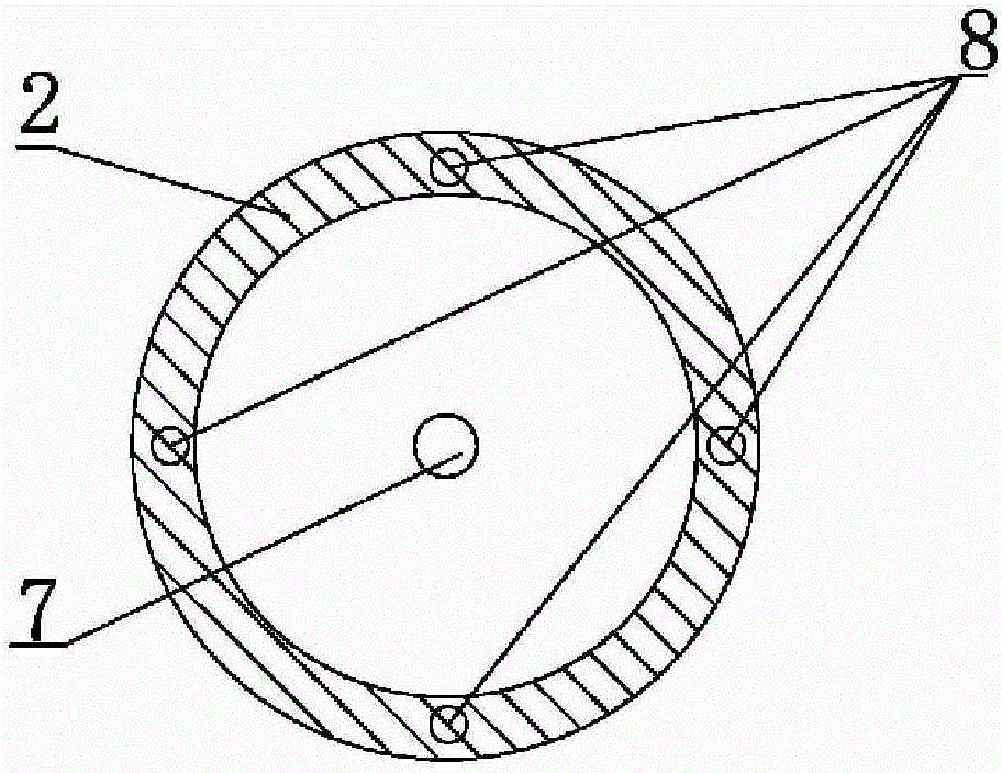
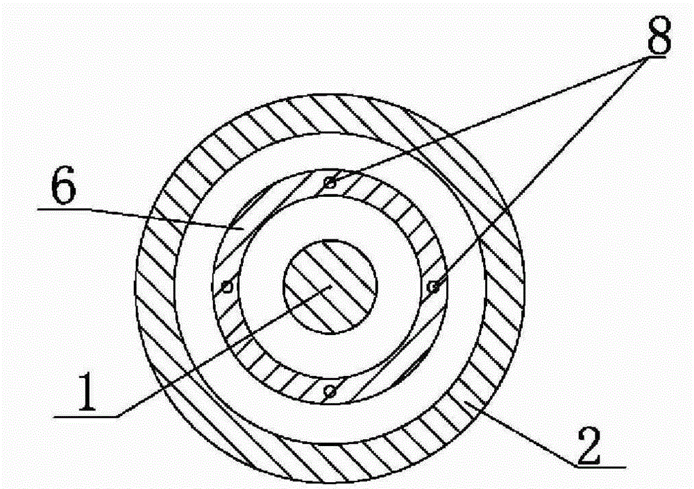
[0033] Embodiment 1: as attached Figures 1 to 3As shown, the difference from the above-mentioned multi-stage piston two-way hydraulic cylinder is that the cylinder body of embodiment 1 includes a fixed cylinder body 2 and a movable cylinder body, and only one level of movable cylinder body is the final movable cylinder body 6, while the final stage movable cylinder body The lower end of the cylinder body 6 is fixed together or integrated with the piston 3 in the fixed cylinder body 2 with its next-level movable cylinder body, and an upward oil passage hole 7 is arranged on the piston 3 to communicate with the upward chamber 4 of the upper and lower cylinder bodies. Its working process is as follows: when the piston rod 1 needs to move upward, high-pressure fluid is injected into the upward cavity 4 through the upward lubricating oil line 9, while the reverse oil line 10 is in the state of discharging high-pressure fluid outward, so that the fixed cylinder 2 Both the piston 3 ...


PUM


Abstract

The invention provides a vertical push-up and pull-down hydraulic pumping unit. A balance tank is positioned in a rack; the bottom of a hydraulic cylinder is fixedly arranged on a pedestal of the rack below the balance tank; the top end of a piston post is arranged together with the bottom end of the balance tank and can make the balance tank move up and down along the inside of the rack; the top of the rack above the balance tank is provided with a fixed pulley; the inner end of an oil pumping platform is arranged on the outer side of the upper part of the rack; a guide pulley is arranged outside the oil pumping platform; and the inner end of an oil pumping rope is fixedly arranged on the balance tank, and the outer end of the oil pumping rope can be fixedly connected with a pumping rod after passing through the fixed pulley and the guide pulley. The vertical press-up and pull-down hydraulic pumping unit has the advantages of reasonable and compact structure, long service life, convenient use, good installability, low energy consumption, low maintenance cost and the like, and also can achieve large travel of the oil pumping unit and increase the running speed of the oil pumping unit. The vertical press-up and pull-down hydraulic pumping unit preferably adopts a basement type in use, so energy consumption can be further reduced, the height of a derrick is reduced, the stability is enhanced and the installation difficulty is lowered.

Description

1. Technical field [0001] The invention relates to the technical field of oil pumping units, and relates to a vertical top-down hydraulic pumping unit. 2. Background technology [0002] Existing pumping units generally include beam pumping units and hydraulic pumping units, etc., and beam pumping units are more traditional pumping units, but there are always the following problems: relatively large structure, relatively large weight, It is difficult to adjust the stroke, stroke times and balance, especially the high energy consumption; the hydraulic pumping unit is a new type of pumping unit that has appeared in the past ten years, but due to its complex structure, short service life, inconvenient use, and maintenance costs High and has not been widely used. 3. Contents of the invention [0003] The present invention provides a vertical up-and-down hydraulic pumping unit, which overcomes the deficiencies of the prior art and solves the problems of complex structure, short...

Claims


Application Information

Patent Timeline
Patent Type & Authority Patents(China)
IPC IPC(8): E21B43/00F04B47/08F04B47/12
Inventor 徐洪德王新愚
Owner 合立智能装备有限责任公司
Why Eureka
Try Eureka