Yarn carrying spindle for controlling bobbin pay-off tension through magnetic damping for knitting machine
What is Al technical title?
Al technical title is built by PatSnap Al team. It summarizes the technical point description of the patent document.
A pay-off tension and magnetic damping technology, applied in woven fabrics, textiles and papermaking, can solve the problems of unstable pay-off tension, uncontrollable tension, insufficient knitting stroke, etc., to ensure product stability, improve quality, The effect of saving manpower
Pending Publication Date: 2021-01-01
XUZHOU HENGHUI BRAIDING MACHINE
View PDF0 Cites 0 Cited by
Summary
Abstract
Description
Claims
Application Information
AI Technical Summary
This helps you quickly interpret patents by identifying the three key elements:
Problems solved by technology
Method used
Benefits of technology
Problems solved by technology
[0005] The purpose of the present invention is to provide a yarn-carrying spindle that uses magnetic damping to control the pay-off tension of the bobbin for a knitting machine, so as to solve the problem of unstable pay-off tension and uncontrollable tension when the existing yarn-carrying spindle is weaving a preform on a knitting machine. Insufficient travel and low efficiency
Method used
Image
Click on the blue label to locate the original text in one second.
Reading with bidirectional positioning of images and text.
Examples
Embodiment 1
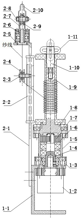
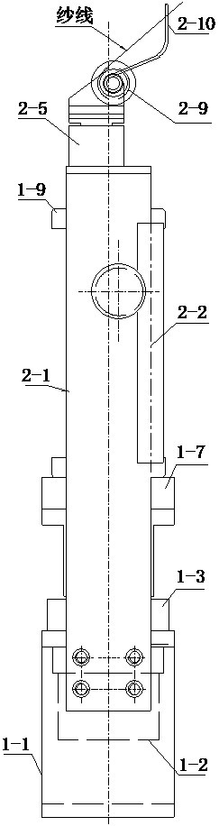
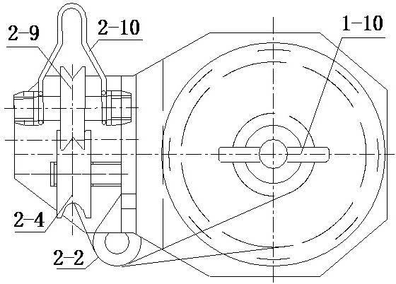
[0030] Embodiment 1: A spinning spindle for controlling the tension of bobbin pay-off by magnetic damping includes: a tension pay-off mechanism 1 and a wire outlet mechanism 2;
[0031] The tension pay-off mechanism 1 includes: a base 1-1, a magnetic damper 1-2, a bearing flange 1-3, a mandrel 1-4, a sheath 1-5, a gasket 1-6, a scroll Spring 1-7, bobbin seat 1-8, bobbin 1-9, bobbin pin 1-10 and bobbin buckle 1-11.
[0032]A magnetic damper 1-2 is installed on the lower part of the upper plane of the base 1-1, and a bearing flange 1-3 is installed on the upper part of the upper plane of the base 1-1; the mandrel 1-4 passes through the center of the bearing flange 1-3 , and installed on the bearing flange 1-3 through the bearing; the output shaft of the magnetic damper 1-2 is inserted into the central hole at the lower end of the mandrel 1-4, and is connected with the mandrel 1-4 as a whole; A sheath 1-5 is installed on the top of the mandrel 1-4 through a bearing, a notch is o...
PUM
Abstract
The invention discloses a yarn carrying spindle for controlling bobbin pay-off tension through magnetic damping for a knitting machine, and belongs to the yarn carrying spindle for controlling the bobbin pay-off tension through the magnetic damping. The yarn carrying spindle comprises a tension pay-off mechanism and a yarn outlet mechanism. The yarn outlet mechanism is fixedly installed at the upper end of one side of the tension pay-off mechanism. The tension pay-off mechanism comprises a base, a magnetic damper, a bearing flange, a mandrel, a sheath, a gasket, a volute spiral spring, a bobbin base, a bobbin, a bobbin pin shaft and a bobbin buckle. The yarn outlet mechanism comprises a vertical rod, a yarn outlet blocking rod, a third wheel shaft, a third wheel, a bearing sleeve, a rotating shaft, a yarn outlet wheel support, a yarn outlet wheel shaft, a yarn outlet wheel and a yarn outlet swing head; one side of the vertical rod is provided with the yarn outlet blocking rod, and thevertical rod is provided with the third wheel; the rotating shaft is installed at the top of the vertical rod and provided with the yarn outlet wheel support; and the yarn outlet wheel and the yarn outlet swing head are installed on the yarn outlet wheel support. The yarn carrying spindle has the advantages that manpower is saved, quality and efficiency are improved, product stability is guaranteed, and the large stroke, constant tension and even knitting pitch of a special knitting machine are achieved.
Description
technical field [0001] The invention relates to a yarn-carrying spindle for a braiding machine, in particular to a yarn-carrying spindle for a braiding machine that uses magnetic damping to control the pay-off tension of a bobbin. Background technique [0002] At present, when many knitting machines weave special fiber materials, they use ordinary spindles to run and weave on the knitting machine. The bobbin carrying spindles is installed vertically. The particularity of the fiber material has high performance requirements for the carrying spindle, including the controllability of the pay-off tension, large stroke, and the stability of the pay-off tension. [0003] Figure 4 The middle is a schematic diagram of the structure of the existing Pu Neng carrying spindle, including: the spindle rod (3-1), the bobbin (3-2), the thread pendant (3-3), the bobbin shaft (3-4), the middle porcelain eye ( 3-5), the line drop porcelain eye (3-6), the outlet porcelain eye (3-7), the brake...
Claims
Application Information
Patent Timeline
Application Date:The date an application was filed.
Publication Date:The date a patent or application was officially published.
First Publication Date:The earliest publication date of a patent with the same application number.
Issue Date:Publication date of the patent grant document.
PCT Entry Date:The Entry date of PCT National Phase.
Estimated Expiry Date:The statutory expiry date of a patent right according to the Patent Law, and it is the longest term of protection that the patent right can achieve without the termination of the patent right due to other reasons(Term extension factor has been taken into account ).
Invalid Date:Actual expiry date is based on effective date or publication date of legal transaction data of invalid patent.