Heat exchanger

A heat exchanger and distributor technology, applied in the field of parallel flow evaporators, can solve problems such as uneven distribution, and achieve the effects of uniform distribution and uniform mixing

Active Publication Date: 2013-07-24
SANHUA(HANGZHOU) MICRO CHANNEL HEAT EXCHANGER CO LTD +1
View PDF0 Cites 0 Cited by
  • Summary
  • Abstract
  • Description
  • Claims
  • Application Information

AI Technical Summary

Problems solved by technology

[0004] Since the opening is close to the inlet of the flat tube 5, the vapor-liquid two-phase refrigerant coming out of the outlet hole is sprayed into the flat tube before it can be evenly mixed in the header, resulting in uneven distribution

Method used


Image

  • Heat exchanger
  • Heat exchanger
  • Heat exchanger

Examples


Embodiment 1

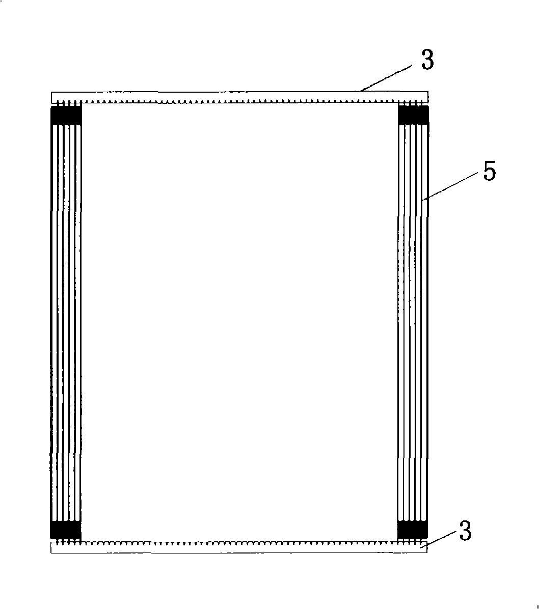
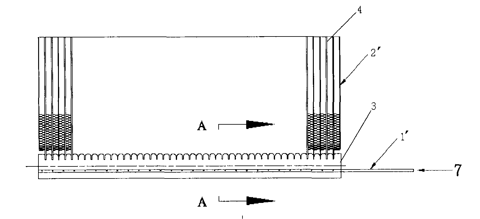
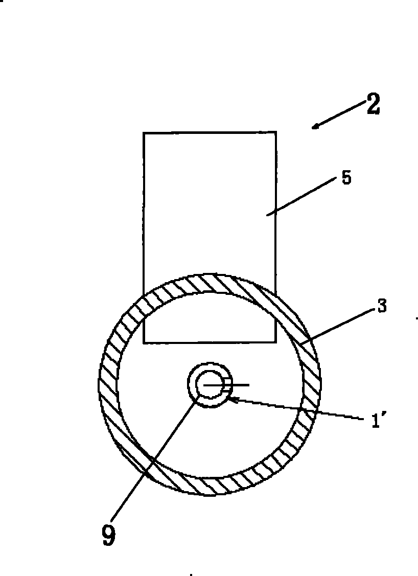
[0029] Figure 4 A schematic diagram showing a partial structure of the parallel flow evaporator 2 according to Embodiment 1 of the present invention. The parallel flow evaporator includes flat tubes 5 as an example of a plurality of fluid channels for heat exchange. The flat tube 5 has a fluid inlet 10 and an outlet. The parallel flow evaporator also includes a header 3 arranged at the end of the flat tube 5 , and the fluid inlet 10 of the flat tube 5 communicates with the header 3 . The parallel flow evaporator also includes a distributor, the distributor includes a distribution pipe 9, the distribution pipe 9 is arranged in the header pipe 3, and the distribution pipe 9 is located far away from the central line of the header pipe 3. One side of the fluid inlet 10 of the flat tube 5.

[0030] Figure 4 In the example in , the parallel flow evaporator is placed upright, and the distribution pipe 9 is arranged in the header 3 on the lower side. At this time, the distributi...

Embodiment 2

[0036] Embodiment 2 is a modification to Embodiment 1, Figure 5a and 5b A schematic diagram showing a partial structure of a parallel flow evaporator 2 according to a second embodiment of the present invention. In this embodiment, on the basis of Embodiment 1, the angle a between the centerline 12 of the outlet hole 8 and the horizontal centerline H satisfies: 5° Figure 5a and 5b shown.

[0037] In the example shown in the figure, for example, Figure 5b Among them, the centerline of the header 3 and the axial centerline 14 of the flat tube 5 are substantially in the same plane. Alternatively, the centerline of the header 3 and the axial centerline of the flat tube 5 may not be in the same plane, for example, they may deviate from each other by a certain distance. For example, the centerline of the header 3 is shifted by a certain distance relative to the axial centerline of the flat tube 5 , thus, the centerline of the header 3 is offset by a certain distance relative to...

Embodiment 3

[0041] Embodiment 3 is a modification to Embodiment 1, Image 6 A schematic diagram showing a partial structure of a parallel flow evaporator 2 according to a third embodiment of the present invention. In this embodiment, on the basis of Embodiment 1, two outlet holes 8 are arranged at substantially the same axial position in the pipe wall of the distribution pipe 9, and the centerlines of the two outlet holes 8 are about the flat tube 5 The axial centerline 14 is substantially symmetrical. The angle b between the centerline 12 of the outlet hole 8 and the axial centerline of the flat tube 5 satisfies the condition: 5°

[0042] In the example shown in the figure, where the parallel flow evaporator is placed upright, the centerlines 12 of the two outlet holes 8 may be symmetrical about the vertical centerline V of the header 3, and the centerlines 12 of the outlet holes 8 The included angle b with the vertical centerline V of the header 3 satisfies the condition: 5° Im...


PUM


Abstract

The invention provides a heat exchanger, which comprises a plurality of fluid channels for heat exchange, header pipes arranged at end parts of the plurality of fluid channels and a distributor, wherein each fluid channel is provided with a fluid inlet; the fluid inlets of the plurality of fluid channels are communicated with the header pipes, and the header pipes are provided with center lines; and the distributor comprises distributing pipes, the distributing pipes are arranged in the header pipes, and the distributing pipes are positioned on one side, far away from the fluid inlets of the plurality of fluid channels, of the center lines. By adopting the structure, the mixed space of vapor-liquid two-phase refrigerant outflowing from an outlet hole is enlarged, so that the mixing is relatively uniform and the distribution of the refrigerant is uniform.

Description

technical field [0001] The present invention relates to a heat exchanger, in particular a parallel flow evaporator. Background technique [0002] like Figure 1a As shown in , the parallel flow evaporator 2' comprises headers 3 arranged on both sides. In the parallel-flow evaporator 2', since the refrigerant at the inlet 7 is in vapor-liquid two-phase, if an unsuitable refrigerant distributor is used, the refrigerant will be distributed unevenly in each flow path 4 . [0003] The conventional distributor 1' adopts a round pipe to be inserted into the header 3, such as Figure 1b As shown, the round tube 9' is located at the center of the header 3 or at the center of another header, and outlet holes 8 of the same size and at the same distance are opened along the length of the distributor in the refrigerant inlet direction of the round tube. And the perforation direction becomes 90 degree angles with flat tube 5 or faces flat tube 5, as figure 2 and 3 shown. [0004] Si...

Claims


Application Information

Patent Timeline
Patent Type & Authority Patents(China)
IPC IPC(8): F28D1/053F28F9/22F25B39/02
CPCF28F9/0273
Inventor 蒋建龙黄宁杰
Owner SANHUA(HANGZHOU) MICRO CHANNEL HEAT EXCHANGER CO LTD
Why Eureka
Try Eureka