Numerical control relief grinding method for enveloping worm hob and machine tool for realizing same

A worm gear hob and relief grinding technology, which is applied in the direction of milling cutters, milling machine equipment, metal processing equipment, etc., can solve the problems of insufficient execution of drawings, difficulty in ensuring consistency, and difficulty in quantitative analysis, etc.

Inactive Publication Date: 2010-08-04
ZHEJIANG UNIV +1
View PDF0 Cites 13 Cited by
  • Summary
  • Abstract
  • Description
  • Claims
  • Application Information

AI Technical Summary

Problems solved by technology

In the prior art, the relief grinding of the hob is mainly processed by hand with an angle grinder, the execution of the drawing is insufficient, the consistency of each tooth processing is difficult to guarantee, and it is difficult to carry out quantitative analysis when a problem occurs, and the quality of the hob is improved. Not guaranteed and improved

Method used


Image

  • Numerical control relief grinding method for enveloping worm hob and machine tool for realizing same
  • Numerical control relief grinding method for enveloping worm hob and machine tool for realizing same
  • Numerical control relief grinding method for enveloping worm hob and machine tool for realizing same

Examples


Embodiment Construction

[0050] The technical solutions of the present invention will be further described below with reference to the accompanying drawings and embodiments.

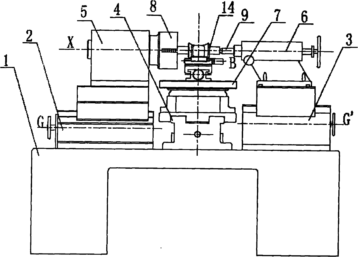
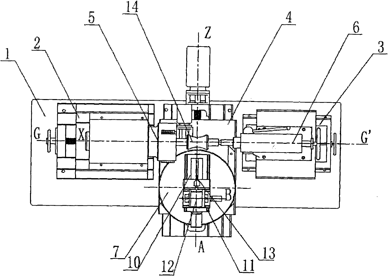
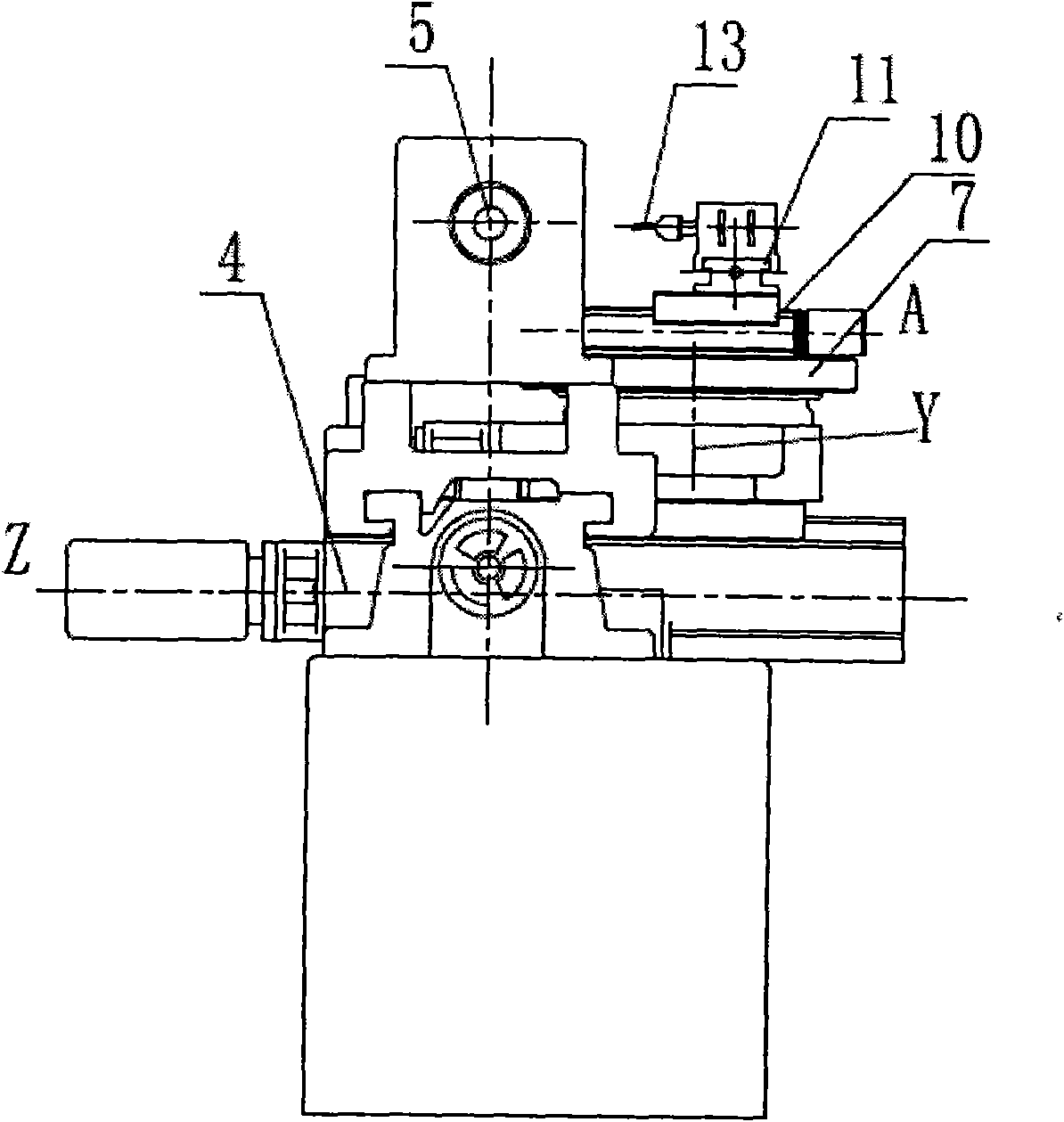
[0051] Such as figure 1 , 2 , 3, the CNC relief grinding machine tool of the toroidal worm gear hob of the present invention mainly comprises a bed 1, a horizontal carriage 2, a tailstock carriage 3, a longitudinal carriage 4, a main shaft support 5, a main shaft 8, and a tailstock 6 and thimble 9. Wherein, the transverse carriage 2, the tailstock carriage 3 and the longitudinal carriage 4 are fixedly installed on the bed 1, the longitudinal carriage 4 is located between the transverse carriage 2 and the tailstock carriage 3, and the transverse carriage 2 The screw rod and the screw rod of the tailstock carriage 3 are parallel to each other, the screw rods of the longitudinal carriage 4 and the horizontal carriage 2 are perpendicular to each other, the main shaft support 5 is fixedly installed on the horizontal carriage 2, and...


PUM


Abstract

The invention discloses a numerical control relief grinding method for an enveloping worm hob and a machine tool. When relief grinding is carried out on side tooth faces of a hob, a main shaft and a rotary disk of the machine tool are synchronously rotated according to a worm pair transmission ratio, the rotation angle of the main shaft is thet0=2s/dl, the main shaft and the rotary disk are synchronously rotated to carry out the relief grinding on the tooth faces of the hob, the rotation angle of the main shaft satisfies the formula1, the transmission ratio of the main shaft and the rotary disk during the relief grinding of the right side tooth faces satisfies the a formula2, and the transmission ratio of the main shaft and the rotary disk during the relief grinding of the left side tooth faces satisfies the formula3, and the rotary disk is re-rotated with a compensation angle to finish the relief grinding of one tooth face, the compensation angle in the process of relief grinding of the right side tooth faces satisfies the formula 4, the compensation angle in the process of the relief grinding of the left side tooth face satisfies the formula 5; and when relief grinding is carried out on tooth backs, the main shaft and the rotary disk are firstly synchronously rotated, wherein the rotation angle of the main shaft is thet0= 2s/dl, the main shaft and the rotary disk are continuously rotated synchronously to enable a longitudinal feed carriage to carry out the relief grinding on the tooth backs along the longitudinal feeding, the rotation angle of the main shaft satisfies the formula 6, then the longitudinal feed carriage is reversely fed, the transmission ratio of the main shaft and the rotary disk is equal to the worm pair transmission ration in the whole process of the relief grinding of the tooth backs, and both the longitudinal feeding and the reverse feeding of the longitudinal feed carriage satisfy the formula7.

Description

technical field [0001] The invention relates to a mechanical processing machine tool, in particular to a shovel grinding machine tool for a numerically controlled toroidal worm gear hob. Background technique [0002] The production of the toroidal worm gear hob mainly includes the following steps: making the hob blank according to the size parameters of the torus worm, grooving the hob and relief grinding the inclination angle of the hob. Relief grinding of the hob gear of the hob is mainly to grind the side cutter surface and the back cutter surface to prevent damage to the tooth surface when processing the worm gear. The relief grinding of the hob hob is difficult to guarantee the processing A process of quality. In the prior art, the relief grinding of the hob is mainly processed manually by using an angle grinder, the execution force of the drawing is insufficient, the consistency of each tooth processing is difficult to guarantee, and it is difficult to carry out quant...

Claims


Application Information

Patent Timeline
Patent Type & Authority Applications(China)
IPC IPC(8): B24B3/12
Inventor 邱清盈舒勤业朱肖虎方普胜张伟谦
Owner ZHEJIANG UNIV
Why Eureka
Try Eureka