Deflection angle multi-line cutting method and cutting device thereof

A multi-line cutting and angle technology, applied in fine working devices, stone processing equipment, manufacturing tools, etc.

Inactive Publication Date: 2010-08-04
JINKO SOLAR CO LTD
View PDF0 Cites 8 Cited by
  • Summary
  • Abstract
  • Description
  • Claims
  • Application Information

AI Technical Summary

Problems solved by technology

Such an operation is in line with the orthodox operation provided by the cutting equipment manufacturer, so few technicians will change this method

Method used


Image

  • Deflection angle multi-line cutting method and cutting device thereof
  • Deflection angle multi-line cutting method and cutting device thereof

Examples


Embodiment 1

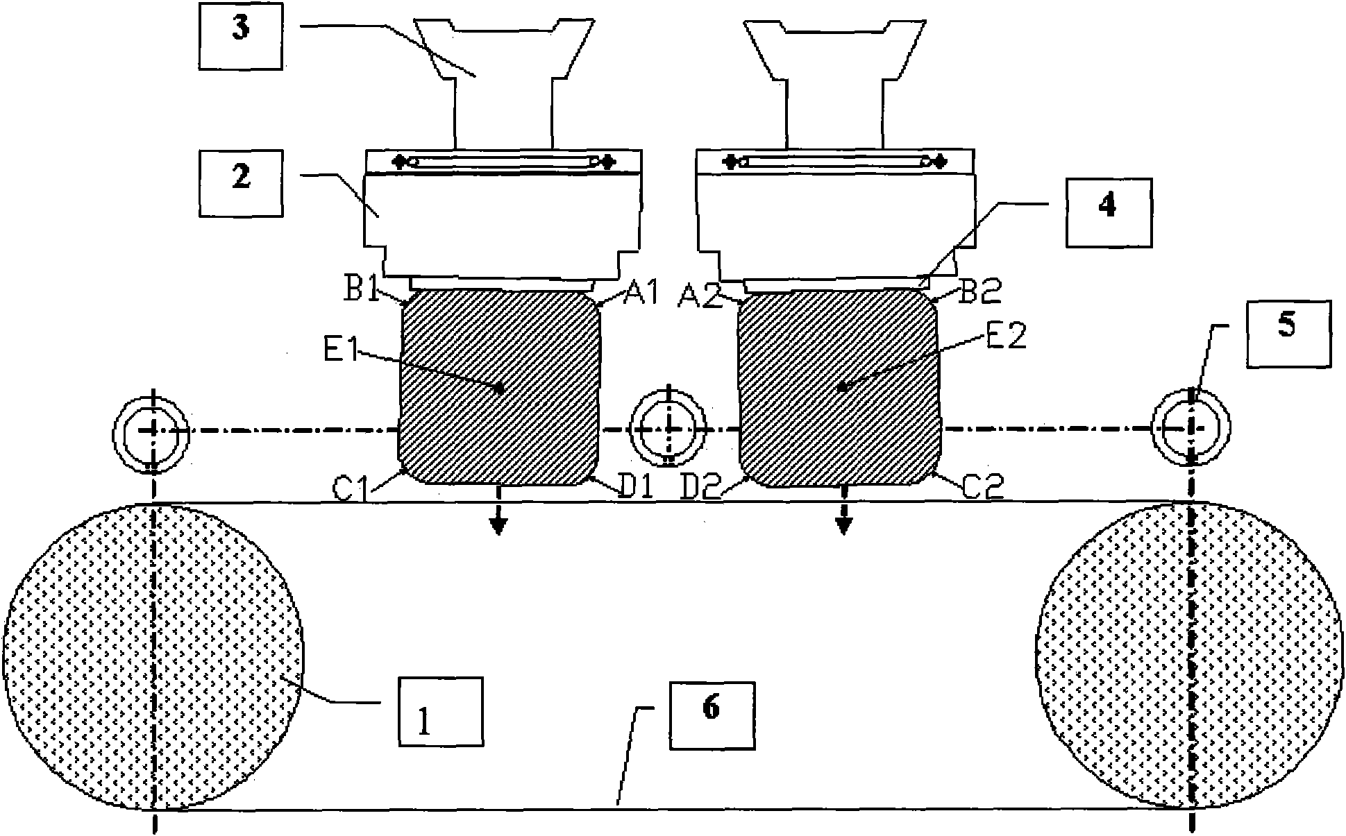
[0031] Embodiment 1, off-angle multi-wire cutting method, multi-wire cutting through chamfering two silicon ingots at the same time, the first silicon ingot and the second silicon ingot are fixed on the dovetail seat 3, the first silicon ingot The central axis E1 of the first silicon ingot is distributed parallel to the central axis E2 of the second silicon ingot, and the cross section of the first silicon ingot along the direction perpendicular to the ground is distributed with a first upper inner vertex angle A1, a first upper outer vertex angle B1, The first lower outer apex angle C1, the first lower inner apex angle D1; the second upper inner apex angle A2, the second upper outer apex angle B2, the second The lower outer vertex angle C2, the second lower inner vertex angle D2; the distance between the first lower outer vertex angle C1 and the horizontal line is higher than the distance between the first lower inner vertex angle D1 and the horizontal line; the second lower o...

Embodiment 2

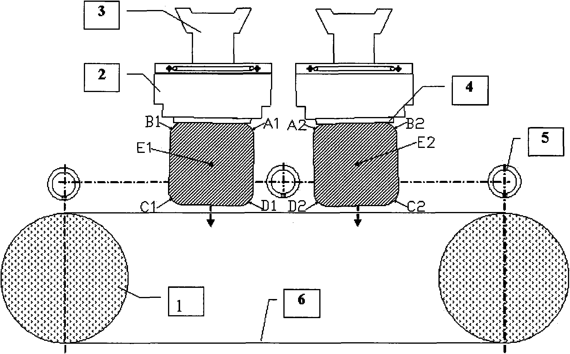
[0032] Embodiment 2, off-angle multi-wire cutting method, multi-wire cutting through chamfering two silicon ingots at the same time, the first silicon ingot and the second silicon ingot are all fixed on the dovetail seat 3, the first silicon ingot The central axis E1 of the first silicon ingot is distributed parallel to the central axis E2 of the second silicon ingot, and the cross section of the first silicon ingot along the direction perpendicular to the ground is distributed with a first upper inner vertex angle A1, a first upper outer vertex angle B1, The first lower outer apex angle C1, the first lower inner apex angle D1; the second upper inner apex angle A2, the second upper outer apex angle B2, the second The lower outer corner C2, the second lower inner corner D2; the distance of the first lower outer corner C1 perpendicular to the horizontal line is 1.6 mm higher than the distance of the first lower inner corner D1 perpendicular to the horizontal line; the second lowe...

Embodiment 3

[0033]Embodiment 3, off-angle multi-wire cutting method, simultaneously multi-wire cutting two silicon ingots processed by chamfering, the first silicon ingot and the second silicon ingot are all fixed on the dovetail seat 3, the first silicon ingot The central axis E1 of the first silicon ingot is distributed parallel to the central axis E2 of the second silicon ingot, and the cross section of the first silicon ingot along the direction perpendicular to the ground is distributed with a first upper inner vertex angle A1, a first upper outer vertex angle B1, The first lower outer apex angle C1, the first lower inner apex angle D1; the second upper inner apex angle A2, the second upper outer apex angle B2, the second The lower outer corner C2, the second lower inner corner D2; the distance of the first lower outer corner C1 perpendicular to the horizontal line is 1.4mm higher than the distance of the first lower inner corner D1 perpendicular to the horizontal line; the second low...


PUM


Abstract

The invention relates to a deflection angle multi-line cutting method and a cutting device thereof. In a method for cutting silicon ingots into a plurality of chips in the traditional process, the first silicon ingot and the second silicon ingot are totally parallel to the horizontal plane during fixing, and the cut lines are parallel to the bottoms of the silicon ingots, so no deflection angle is formed. The deflection angle multi-line cutting method of the invention cuts the two silicon ingots subjected to chamfering treatment in a multi-line mode at the same time. By adopting the method of the invention, the reduction of cutting time by 10 to 20 minutes from the traditional 430 minutes has great significance, for a certain working time needs to be consumed during detaching the cut silicon chips and replacing new cut lines; if the detachment and replacement consume over-long time and the time is converted into the cutting time of about 7 hours, the total working period exceeds 8 hours, and the working mode of three shifts made every 8 hours each day can be converted into a mode of two shifts in the effective working period; thus, enough time is left for preparing a next cutting operation.

Description

technical field [0001] The invention relates to a multi-wire saw cutting method and a cutting device thereof, in particular to an off-angle multi-wire saw cutting method and a cutting device thereof. Background technique [0002] In the traditional process, the method of cutting silicon ingots into multiple silicon wafers is not biased, as follows: [0003] The method of cutting a silicon ingot into multiple silicon wafers in the traditional process, while cutting two chamfered silicon ingots with multiple wires, the first silicon ingot and the second silicon ingot are fixed on the dovetail 3, and the second The central axis E1 of one silicon ingot is distributed parallel to the central axis E2 of the second silicon ingot. The cross-section of the first silicon ingot along the direction vertical to the ground is distributed with a first upper inner vertex angle A1 and a first upper outer corner. Apex angle B1, first lower outer apex angle C1, first lower inner apex angle D1...

Claims


Application Information

Patent Timeline
Patent Type & Authority Applications(China)
IPC IPC(8): B28D5/04
Inventor 徐永兵喻飞建徐志群
Owner JINKO SOLAR CO LTD
Why Eureka
Try Eureka