A large capacitance micro-inertial sensor based on synovial damping and its manufacturing method

A micro-inertial sensor, sliding film damping technology, applied in the photoengraving process of the pattern surface, the process for producing decorative surface effects, piezoelectric / electrostrictive / magnetostrictive devices and other directions, can solve the problem of increasing the sensor Problems such as mechanical noise, large air damping of the lamination film, increase in the mass of the sensor vibrator and reduction in the distance between the plates, to achieve the effect of improving the mechanical noise and reducing the distance

Inactive Publication Date: 2011-12-21
HANGZHOU DIANZI UNIV
View PDF0 Cites 0 Cited by
  • Summary
  • Abstract
  • Description
  • Claims
  • Application Information

AI Technical Summary

Problems solved by technology

For comb-shaped capacitive sensors processed by bulk silicon technology such as deep reactive particle etching (Deep RIE), the aspect ratio of the plate capacitance is generally less than 30:1, which limits the increase in the mass of the sensor vibrator and the Reduced plate spacing
For small-pitch plate capacitors, the pressure film air damping is relatively large, which increases the mechanical noise of the sensor

Method used


Image

  • A large capacitance micro-inertial sensor based on synovial damping and its manufacturing method
  • A large capacitance micro-inertial sensor based on synovial damping and its manufacturing method
  • A large capacitance micro-inertial sensor based on synovial damping and its manufacturing method

Examples


Embodiment Construction

[0035] The present invention will be further described below in conjunction with the embodiments and accompanying drawings, but the present invention is by no means limited to the described embodiments.

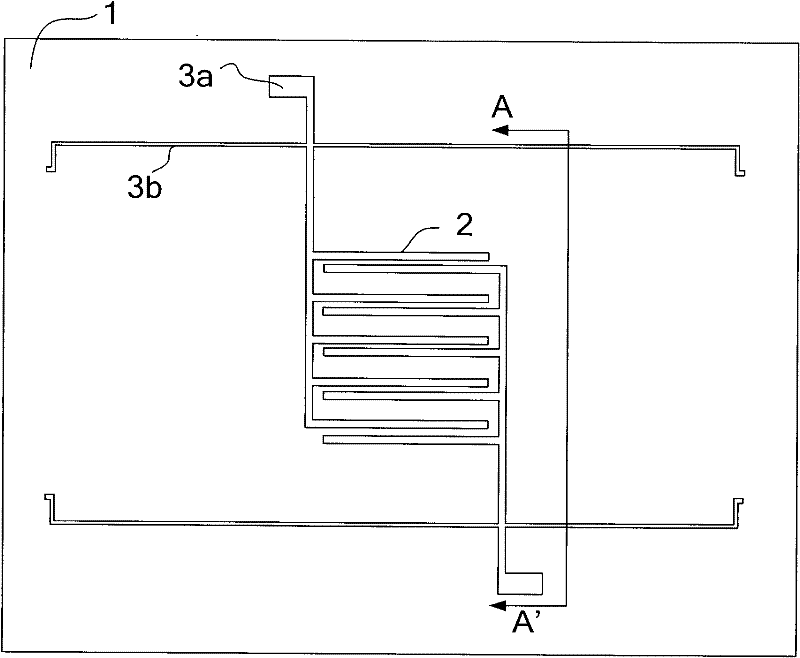
[0036] Embodiments of the present invention relate to a capacitive micro-inertial sensor, such as figure 1 As shown, the first substrate 1 is formed on the first substrate 1 with intersecting comb-shaped fixed counter electrodes, the fixed lead electrodes 3a are connected to the silicon strip group connection lines 3b corresponding to two groups of silicon strip groups, and the fixed counter electrodes are composed of ten combs arranged transversely Composed of tooth electrodes 2, a total of five pairs of comb-tooth electrodes; fixed lead electrodes are symmetrically arranged on both sides of the fixed counter electrodes, and the silicon strip group connecting lines arranged horizontally are connected to the fixed lead electrodes.

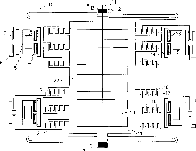
[0037] Such as figure 2 As shown, the ancho...


PUM


Abstract

The invention relates to a large-capacitance micro-inertial sensor based on synovial film damping and a manufacturing method thereof. The existing sensors have large noise, poor stability, and small range and bandwidth. In the sensor of the present invention, silicon strip groups are symmetrically arranged on both sides of the sensor mass block, sensor anchor points are arranged at both ends of the sensor mass block, and grid-shaped electrodes are arranged inside the sensor mass block; the driver mass block corresponds to the silicon strip group Setting; a fixed counter electrode is set on the first substrate under the mass block of the sensor. The method for manufacturing the sensor is firstly to form a fixed counter electrode on the first substrate; secondly, to form an electrical insulating layer on the upper surface of the second substrate, and to form a suspension area on the lower surface; then to bond the two substrates; and finally to etch to form the sensor. The micro-inertial sensor in the invention has novel structure, high resolution and sensitivity, simple manufacturing process, and is beneficial to reduce cost and improve yield.

Description

technical field [0001] The invention belongs to the field of micro-electromechanical technology, and relates to a micro-inertial sensor, in particular to a large-capacitance micro-inertial sensor based on synovial film damping and a manufacturing method thereof. Background technique [0002] In recent ten years, accelerometers made with micromechanical technology have been developed rapidly. Its main acceleration detection technologies include piezoresistive detection, piezoelectric detection, thermal detection, resonance detection, electromagnetic detection, light detection, tunnel current detection and capacitance detection. In addition, there are accelerometers based on other detection technologies, such as optical accelerometers, electromagnetic accelerometers, and capacitive accelerometers. The development of optical accelerometers is mainly to combine the advantages of light and micromechanics to make sensors with high electromagnetic shielding or good linearity. Amo...

Claims


Application Information

Patent Timeline
Patent Type & Authority Patents(China)
IPC IPC(8): B81B7/02B81C1/00B81C3/00G01P15/125
Inventor 董林玺颜海霞
Owner HANGZHOU DIANZI UNIV
Why Eureka
Try Eureka