Micro-structure adhesive tape

A technology of microstructure and adhesive tape, which is applied in the direction of adhesives, film/sheet adhesives, etc., can solve the problems of increasing the number of light-emitting diodes arranged, poor control of microstructure injection, uneven development of light guide plates, etc., to reduce the development Non-uniformity, easy production, and low-cost effects

Inactive Publication Date: 2010-08-04
AU OPTRONICS CORP
View PDF0 Cites 9 Cited by
  • Summary
  • Abstract
  • Description
  • Claims
  • Application Information

AI Technical Summary

Problems solved by technology

However, unlike cold cathode ray tubes, light-emitting diodes are point light sources, and when point light sources are used, uneven development of the light guide plate will occur (Mura)
[0004] At present, the method to reduce uneven development is to reduce the distance between LEDs, but this method will inevitably increase the number of LEDs arranged, and the cost will increase proportionally.
Secondly, microstructures are added to the plane of the light guide plate on the light incident side, but the injection of the microstructures is not easy to control during the production process of the light guide plate, and cannot be 100% formed, and this production process must increase the cost of mold manufacturing

Method used


Image

  • Micro-structure adhesive tape
  • Micro-structure adhesive tape
  • Micro-structure adhesive tape

Examples


Embodiment Construction

[0034] The following will clearly illustrate the spirit of the present invention with the accompanying drawings and detailed descriptions. After understanding the preferred embodiments of the present invention, any person of ordinary skill in the art can make changes and modifications based on the technology disclosed in the present invention, and without departing from the spirit and scope of the present invention.

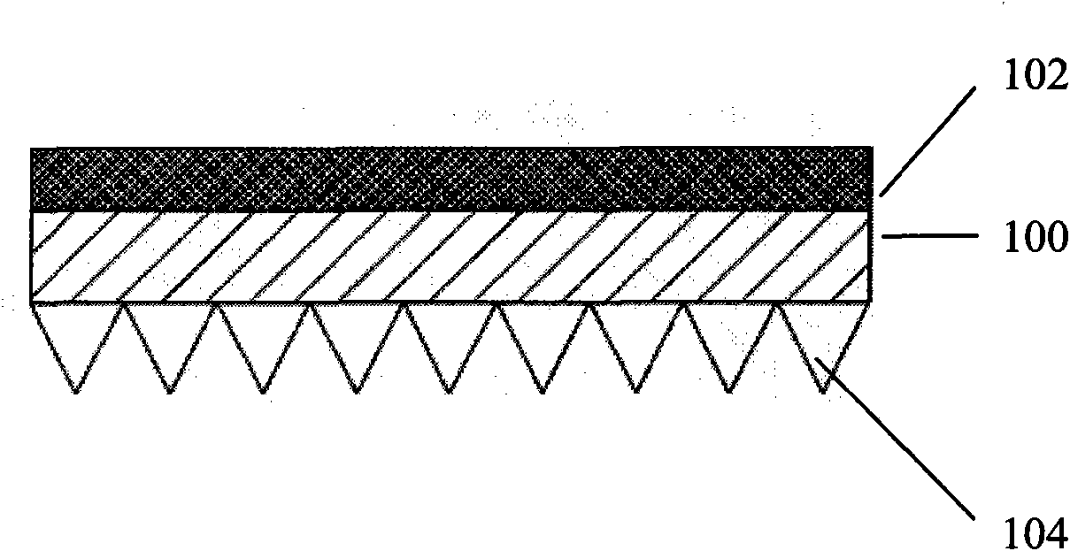
[0035] The invention relates to a microstructure adhesive tape, which comprises: a base material layer and an adhesive layer. There are multiple microstructures on one side of the substrate layer, and the adhesive layer is coated on the other side of the substrate layer. When in use, the adhesive layer of the adhesive tape is adhered to the side of the light guide plate to reduce the phenomenon of uneven development.

[0036] refer to figure 1 , which is a cross-sectional view illustrating an embodiment of the microstructure adhesive tape of the present inventi...


PUM


Abstract

The invention provides a micro-structure adhesive tape which is applicable to being attached on a light incidence surface of a light guide plate, comprising a base material layer and a binding agent layer, wherein one side of the base material layer is provided with a plurality of micro structures, and the binding agent layer is coated on the other side of the base material layer. The micro-structure adhesive tape can reduce the phenomenon of uneven development on the light guide plate, thus reducing the using quantity of light sources and lowering the production cost.

Description

technical field [0001] The invention relates to a microstructure adhesive tape, in particular to a microstructure adhesive tape suitable for affixing a light incident surface of a light guide plate. Background technique [0002] Recently, the continuous innovation of optoelectronic technology, coupled with the arrival of the digital age, has promoted the vigorous development of the liquid crystal display market. Liquid crystal displays have many advantages such as high image quality, small size, light weight, low driving voltage and low power consumption. Therefore, it is widely used in consumer communication or electronic products such as personal digital assistants (PDAs), mobile phones, video recorders, notebook computers, desktop monitors, car monitors, and projection TVs, and gradually replaces cathodes. Ray tubes became the mainstream of displays. In order to meet the demand for thinner and lighter liquid crystal displays, especially when used on notebooks, the light...

Claims


Application Information

Patent Timeline
Patent Type & Authority Applications(China)
IPC IPC(8): C09J7/02
Inventor 吴威宏李泓卓黄冠富
Owner AU OPTRONICS CORP
Why Eureka
Try Eureka