Device for driving opening/closing body for vehicle

A technology for driving devices and opening and closing bodies, which is applied to vehicle parts, manual mechanisms, transportation and packaging, etc., and can solve the problems of large number of parts, inability to detect, and increased number of parts

Inactive Publication Date: 2010-08-04
AISIN SEIKI KK
View PDF2 Cites 0 Cited by
  • Summary
  • Abstract
  • Description
  • Claims
  • Application Information

AI Technical Summary

Problems solved by technology

[0012] In this regard, in the vehicle opening and closing body driving device described in Patent Document 1, a mechanism for properly maintaining the tension of the rope and a mechanism for adjusting the initial tension when the rope is installed are respectively provided, so the number of parts is large, and the production cost increase
In addition, when arranging the rope, it is necessary to tighten the nut while adjusting the height position of the tension housing, and then loosen the nut again after the rope is arranging, so the arranging operation is cumbersome
[0013] In addition, in the entrapment detection mechanism described in Patent Document 2, since only the entrapment of the part where the contact sensor is provided can be detected, if another object is entrapped and does not come into contact with the contact sensor, the above-mentioned detection cannot be detected. Happening
[0014] In addition, in the entrapment detection mechanism described in Patent Document 3, since the entrapment of other objects is detected according to the change in the tension of the rope, it can detect entrapment at any entrapment position, but it is necessary to provide a limit switch and a limit switch. Action parts for bit switch action, increasing the number of parts
In addition, there is a problem that it is difficult to downsize due to the need to provide a space for the tension arm to rotate

Method used


Image

  • Device for driving opening/closing body for vehicle
  • Device for driving opening/closing body for vehicle
  • Device for driving opening/closing body for vehicle

Examples


no. 1 approach 〕

[0062] The first embodiment of the present invention will be described with reference to the drawings.

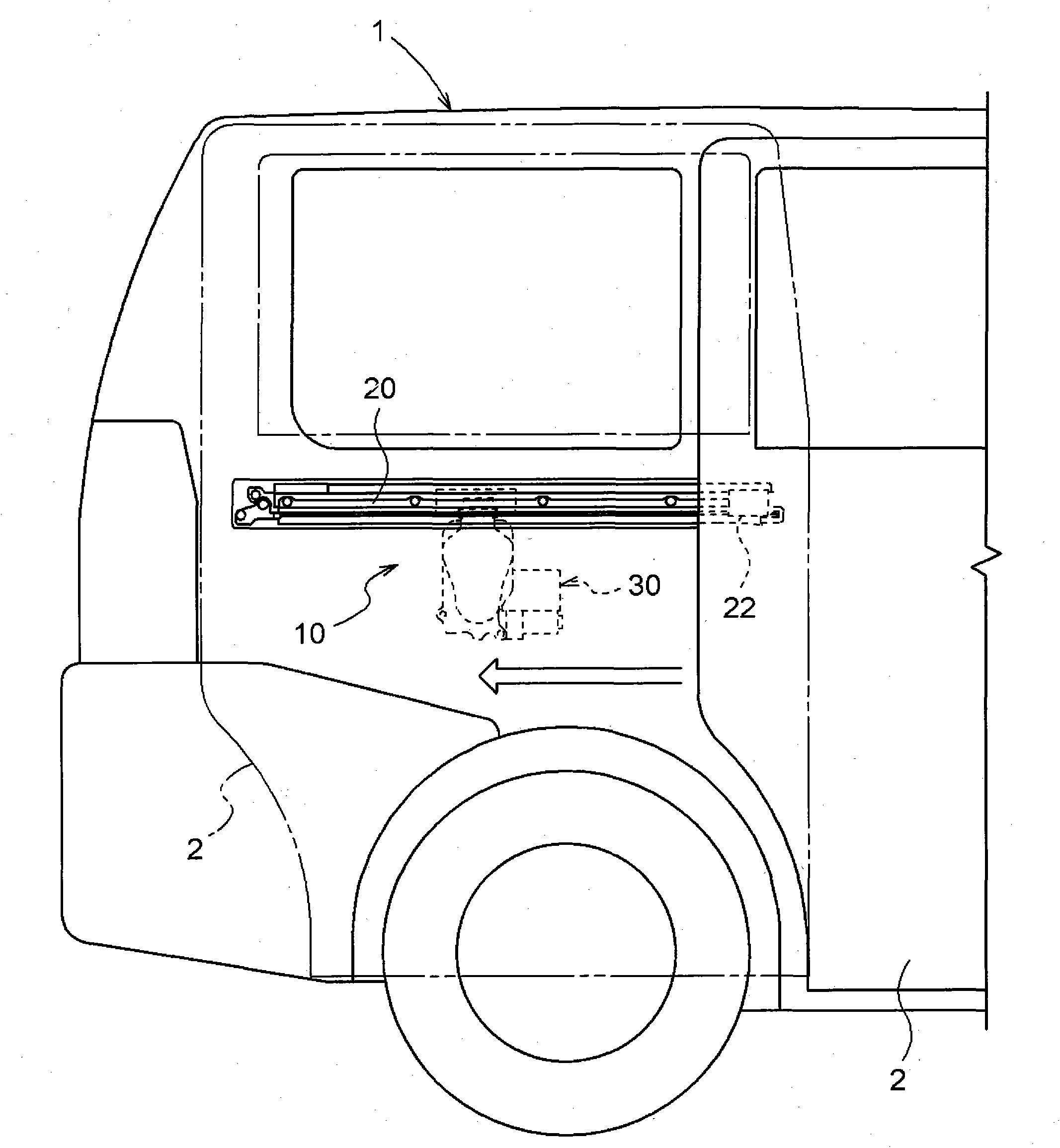
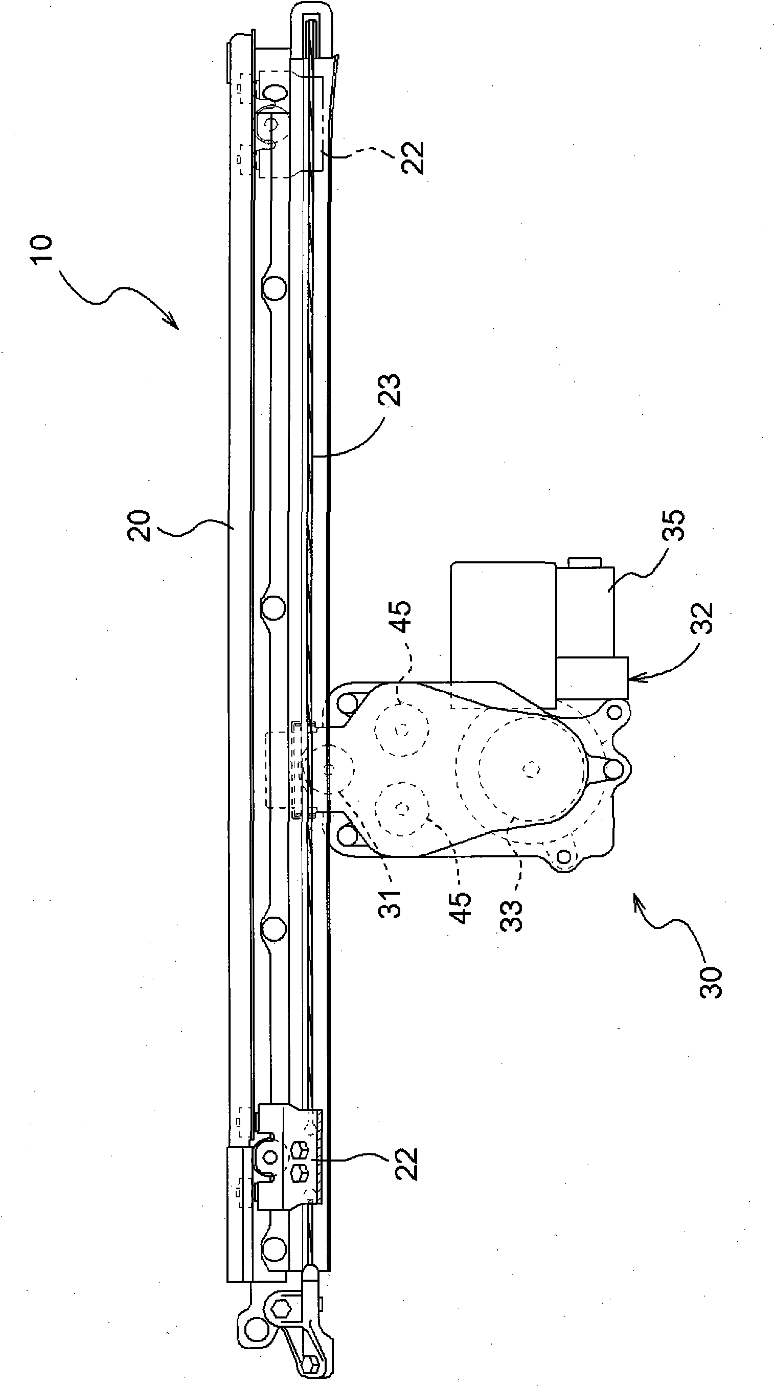
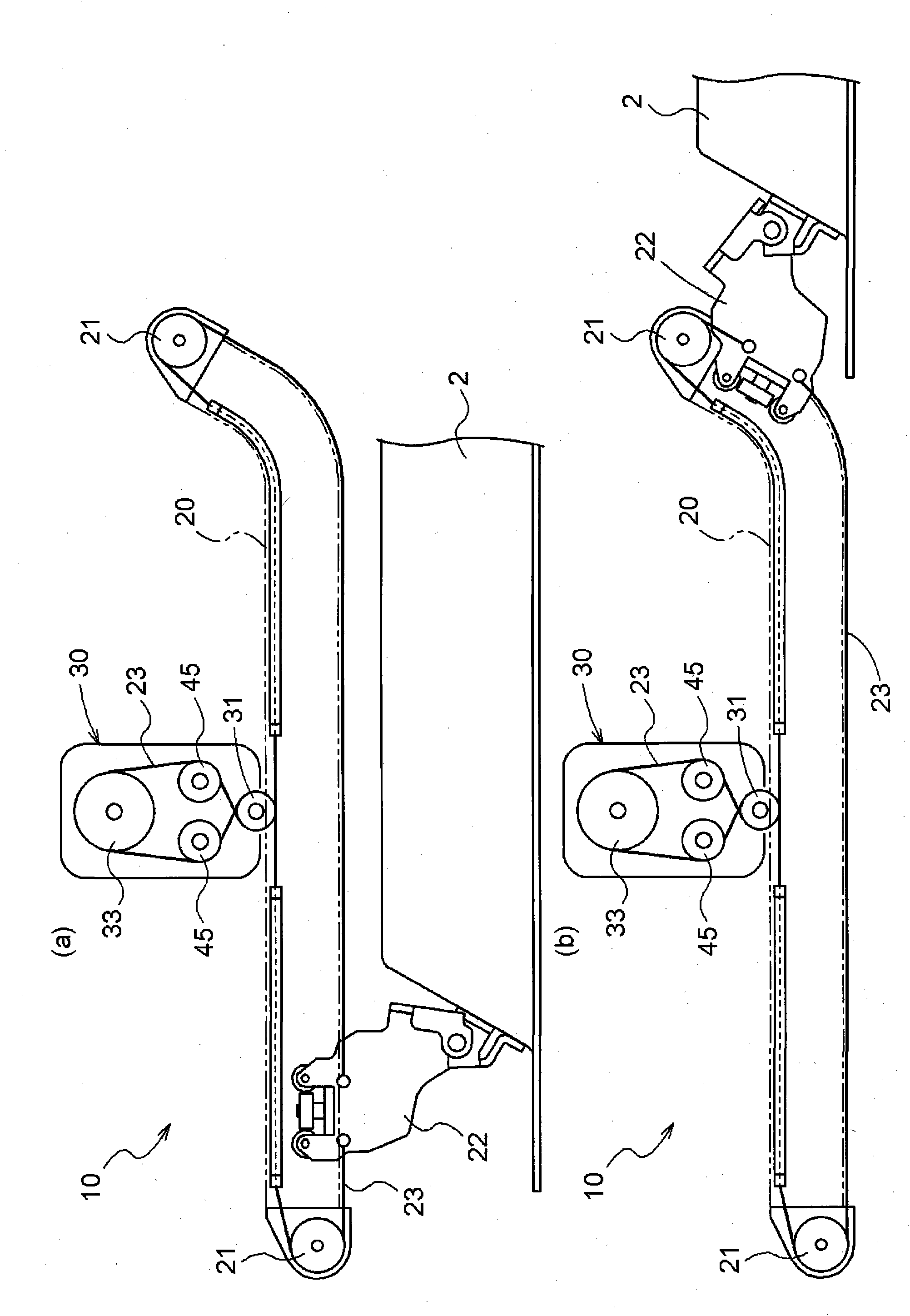
[0063] figure 1 It is a side view of a vehicle 1 having a sliding door 2 as an example of an opening and closing body. This vehicle 1 has a vehicle door opening and closing device 10 as an example of a vehicle opening and closing body drive device, and can automatically perform opening and closing operations of the sliding door 2. figure 2 Is a side view of the vehicle door opening and closing device 10, image 3 Is its top view. In addition, in image 3 Here, the drive unit 30 is schematically shown for easy understanding of the operation of the drive unit 30. As shown in the above figures, the vehicle door opening and closing device 10 has a guide rail 20 and a drive unit 30.

[0064] The guide rail 20 is provided near the center in the height direction of the side surface of the vehicle 1, and the drive unit 30 is suspended from the guide rail 20 in the middle part of the f...

no. 2 approach 〕

[0085] The second embodiment of the present invention will be described with reference to the drawings. Picture 10 It is a schematic diagram of the drive unit 30 related to this embodiment. As shown in the figure, the tension mechanism 40 of the drive unit 30 also has a freely elastically deformable plate spring 42 fixed to the pulley cover 41 supporting the guide pulley 31, and a strain gauge 80 is provided on the plate spring. However, the shape of the pulley cover 41, the position of the fixed plate spring 42, and the location where the strain gauge 80 is installed are different. These differences are explained below.

[0086] In this embodiment, the pulley cover 41 is provided so as to cover the guide pulley 31 not only in the left-right direction but also to the lower side. At this time, in order to facilitate the receiving and releasing of the rope 23 without being blocked by the pulley cover 41, the lower end of the pulley cover 41 is fixed to the bottom plate 36 inside ...

no. 3 approach 〕

[0091] The third embodiment of the present invention will be described with reference to the drawings. Picture 11 It is a schematic diagram of the drive unit 30 related to this embodiment. The configuration of the tension mechanism 40 having the drive unit 30 is substantially the same as the configuration of the tension mechanism 40 described in the second embodiment, but the configuration of the end portion on the free end side of the plate spring 42 is different. The difference will be described below.

[0092] In this embodiment, the rope 23 is directly engaged with the leaf spring 42, and the tension pulley 45 is not provided at the end of each free end side of the leaf spring 42. Here, a bent portion 60 that is bent inward, that is, in a direction opposite to the direction in which the tension is applied, is formed at the end portion on the free end side of the leaf spring 42. In addition, such as Picture 12 As shown, a guide groove 61 for guiding the rope 23 is provided ...


PUM


Abstract

A device for driving an opening / closing body for a vehicle. The device uses a reduced number of parts to reduce cost and can appropriately apply a tensile force to a cable. Further, the device allows the cable to be arranged with a reduced workload to facilitate mounting of the cable. The device has the cable engaged to a support body in order to open and close the opening / closing body; a drive mechanism having a drive wheel and reciprocating the cable; a guide member for guiding the cable, extending from a door, to the drive wheel and guiding the cable, having passed the drive wheel, back to the door; a support member for supporting one of the guide member and the drive wheel; and a tensile force application member fixed to the support member and applying a tensile force to the cable.

Description

Technical field [0001] The present invention relates to a vehicle opening and closing body driving device that drives an opening and closing body provided in a vehicle. Specifically, the present invention relates to a vehicle opening / closing body drive device having: a rope that is locked to an opening / closing body provided in a vehicle to open and close the opening / closing body; a drive unit, It has a driving wheel and a guide member, the driving wheel winds the rope and reciprocating the rope corresponding to the direction of rotation thereof, the guide member guides the rope extending from the opening and closing body to the driving wheel, and The rope that has passed the drive wheel is guided to the opening and closing body again. Background technique [0002] Conventionally, as a vehicle opening / closing body driving device for opening and closing a sliding door provided on the side of a vehicle, it is known to have a rope that is locked to the sliding door at both ends, and...

Claims


Application Information

Patent Timeline
Patent Type & Authority Applications(China)
IPC IPC(8): B60J5/06B60J1/17E05F11/54E05F15/14
CPCE05F15/146B60J5/06E05Y2900/531E05F15/646
Inventor 竹内务石田俊彦
Owner AISIN SEIKI KK
Why Eureka
Try Eureka