Liquid paint pumping apparatus

A pumping equipment and liquid technology, which is applied in the field of pumping liquid paint equipment, can solve problems such as ball wear and leakage, and achieve the effects of reduced wear, reduced noise, and easy replacement

Active Publication Date: 2010-08-04
FINISHING BRANDS UK
View PDF6 Cites 10 Cited by
  • Summary
  • Abstract
  • Description
  • Claims
  • Application Information

AI Technical Summary

Problems solved by technology

However, the use of a spring in contact with the ball adds yet another problem of ball wear and leakage

Method used


Image

  • Liquid paint pumping apparatus
  • Liquid paint pumping apparatus
  • Liquid paint pumping apparatus

Examples


Embodiment Construction

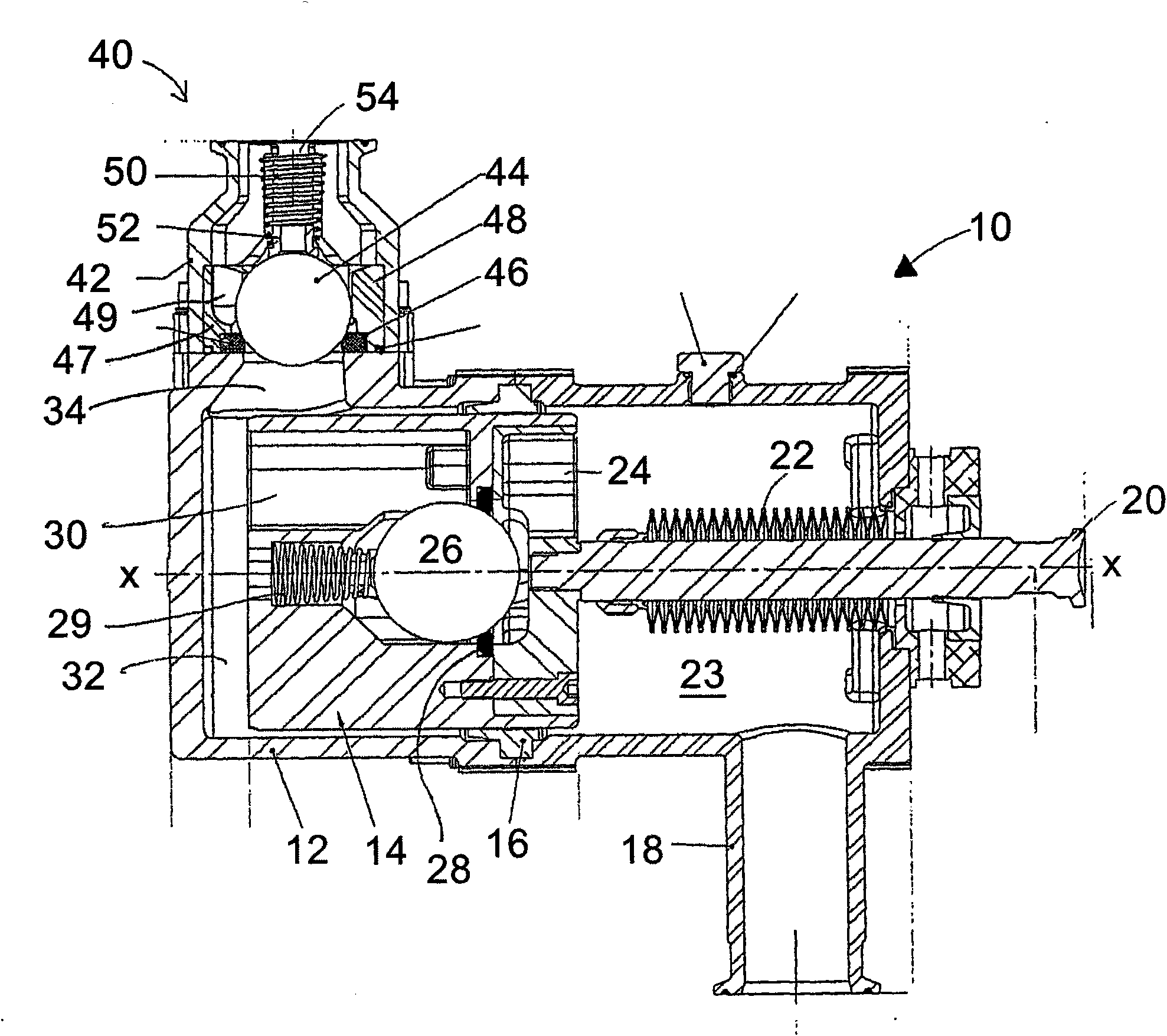
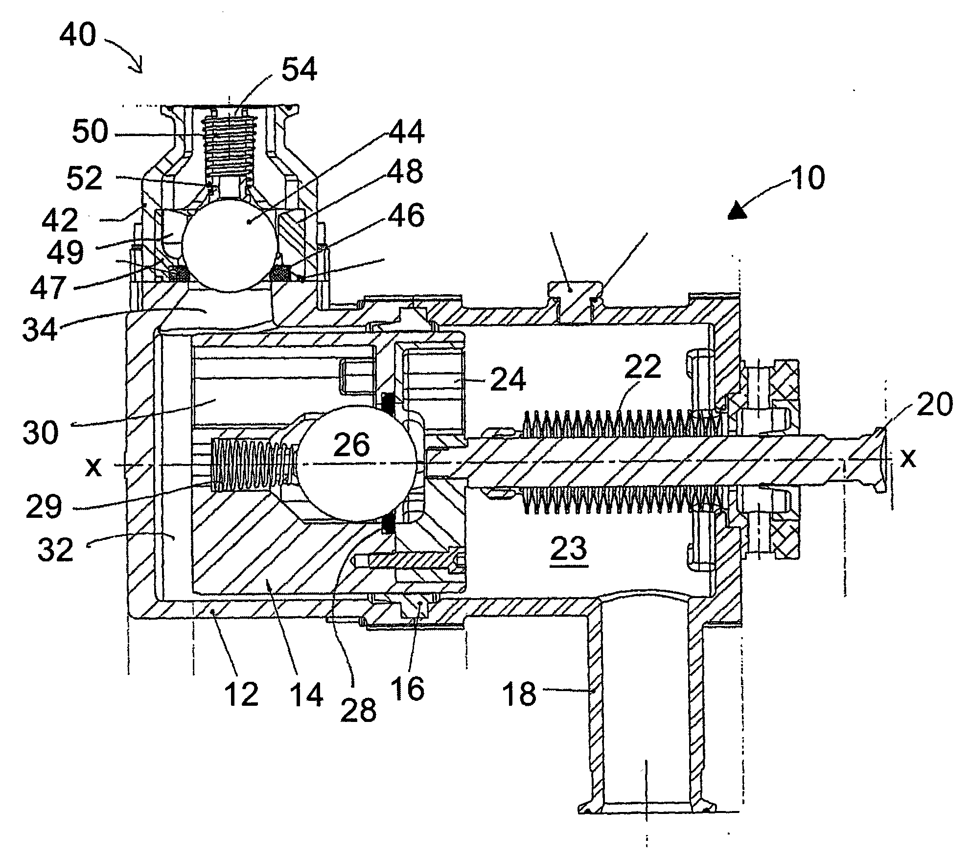
[0025] refer to figure 1 , The paint pumping device 10 includes a cylinder liner 12 in which a piston 14 is installed for reciprocating movement along the axis X-X. Annular seal ring 16 forms a seal between cylinder liner 12 and piston 14 . The cylinder liner is provided with an inlet port 18 for connection to a liquid paint supply. Piston 14 is connected to shaft 20, which is driven in a reciprocating manner by drive means (not shown). A bellows seal 22 forms a seal with the cylinder 12 about the shaft 20 .

[0026] An inlet check valve arrangement is located in the structure of the piston 14 which includes a ball member 26 which is biased towards a contact seat 28 by a helical compression spring. Inlet check valve device (in figure 1 In the position shown in ) a seal is provided between the inlet side channel 24 and the outlet side channel 30 . Inlet side passage through to figure 1 A space 23 to the right of the middle piston 14 is in fluid communication with the inle...


PUM


Abstract

The invention relates to a liquid paint pumping apparatus comprising a piston reciprocable in a cylinder to pump liquid paint during a substantially horizontal pumping stroke of the piston and to charge the cylinder with paint during a reverse stroke of the piston. The apparatus further comprises a check valve disposed within the piston, the check valve comprising: a ball member, a seat, a spring urging the ball member into engagement with the seat, and a plastics cage guiding movement of the ball towards and away from the seat. The seat receives the ball member so as to form a seal to prevent flow of liquid paint between the ball and the seat during the pumping stroke of the piston, and the ball member moves away from the seat during the reverse stroke of the piston.

Description

technical field [0001] The present invention relates to apparatus for pumping liquid paint and more particularly, but not exclusively, to check valves for use in pumping apparatus for liquid paint. Background technique [0002] Reciprocating paint pumps are widely used to provide a stream of pressurized liquid paint to spray booths and the like, particularly in automotive refinishing shops. These pumps use a piston that reciprocates inside a cylinder. During the first stroke of the piston, paint is drawn through the inlet port into the cylinder chamber. During the second reverse stroke of the piston, the paint is pumped out of the chamber through the outlet port. To prevent paint from being pumped through the inlet port, or sucked back through the outlet port, an automatic check valve is provided. Thus, for example, a check valve in the outlet port is configured to automatically open under the influence of paint pressure from the pump during the second stroke of the pisto...

Claims


Application Information

Patent Timeline
Patent Type & Authority Applications(China)
IPC IPC(8): F04B53/12F04B53/10F04B15/02F16K15/04
CPCF16K15/044F16K15/183F04B15/02F04B53/126F04B53/1007F16K15/1823
Inventor 奈杰尔·伍德阿兰·史密斯
Owner FINISHING BRANDS UK
Why Eureka
Try Eureka