
Clamp

A clamp and moving clamp technology, applied in workpiece clamping devices, manufacturing tools, etc., can solve the problems of increasing volume, decreasing clamping force and precision, increasing manufacturing cost, etc. Straight and stable, improving the effect of clamping accuracy

Active Publication Date: 2010-08-11
SUZHOU KINKALTECK MACHINERY TECH
View PDF6 Cites 6 Cited by
  • Summary
  • Abstract
  • Description
  • Claims
  • Application Information

AI Technical Summary

Problems solved by technology

In this way, the volume of the entire clamp is too large, and the clamping force and precision are greatly reduced; moreover, in some equipment that can be made very compact in structure, in order to install this clamp, the volume has to be increased. , not only makes the whole device appear bulky, but also increases the manufacturing cost

Method used


Image

  • Clamp
  • Clamp
  • Clamp

Examples


Embodiment Construction

[0013] Specific embodiments of the present invention will be described in detail below in conjunction with the accompanying drawings.

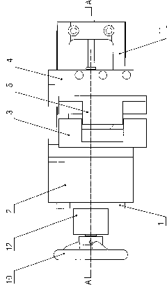
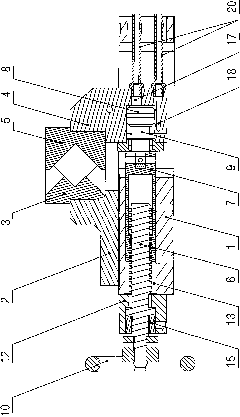
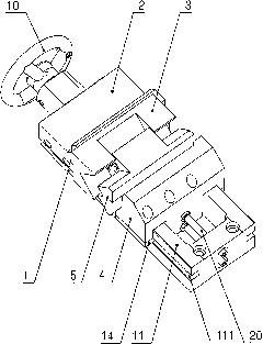
[0014] Such as figure 1 , figure 2 and image 3 As shown, the clamp of the present invention includes: a base 1, a fixed jaw seat 2 fixed on the base 1, and a movable jaw seat 4 slidably arranged on the base 1, and the fixed jaw seat 2 is provided with a fixed jaw body 3. The movable jaw body 5 is provided with the movable jaw body 5 matched with the fixed jaw body 3 on the movable jaw seat 4, and the screw rod adjusting device is arranged in the base 1, and the specific setting method is as follows: the guide hole 13 is arranged in the base 1, and the guide hole 13 is arranged in the base 1 to guide A screw 6 and an adjustment seat 7 are movable in the hole 13, one end of the screw 6 is set in the adjustment seat 7 through threads, and the other end of the screw 6 is movably arranged on the screw support fixed on the base 1 through a beari...


PUM


Abstract

The invention discloses a clamp which has compact structure and high clamping strength and precision. The clamp comprises a pedestal, a fixed clamp jaw base and a movable clamp jaw base. The fixed clamp jaw base is fixed on the pedestal; the movable clamp jaw base is movably arranged on the pedestal; a fixed clamp jaw body is arranged on the fixed clamp jaw base; a movable clamp jaw body which matches with the fixed clamp jaw body is arranged on the movable clamp jaw base; a screw rod adjusting device is arranged in the pedestal; a piston cavity is arranged in the movable clamp jaw base; a piston is arranged in the piston cavity, and the piston cavity is divided into a front oil cavity and a rear oil cavity by the piston; two oil channels which are respectively communicated with the frontoil cavity and the rear oil cavity are arranged in the movable clamp jaw base; oil pipe joints are arranged at the oil channels; one side of the piston is provided with a piston rod; and the piston rod is connected with the screw rod adjusting device. The clamp adopts internally-mounted oil cylinder, thereby having very compact structure. In addition, the clamp can clamp the workpiece tightly without supporting the internally-mounted oil cylinder by adopting a long guiding rod. Moreover, the point of the application of the hydraulic force is close to the jaw of the clamp, thus the clamp has higher clamping strength and precision.

Description

technical field [0001] The invention relates to a clamp, in particular to a clamp driven by an oil cylinder. Background technique [0002] At present, the traditional tongs driven by oil cylinders adopt the structure of the finished oil cylinder. The oil cylinder needs a longer guide rod and more connectors to connect with the movable jaw body in the clamp to drive the movable jaw body. Move back and forth relative to the fixed jaw body. In this way, the volume of the entire clamp is too large, and the clamping force and precision are greatly reduced; moreover, in some equipment that can be made very compact in structure, in order to install this clamp, the volume has to be increased. , not only makes the whole device seem cumbersome, but also increases the manufacturing cost. Contents of the invention [0003] The technical problem to be solved by the present invention is to provide a clamp with compact structure, which can improve clamping strength and precision. [0...

Claims


Application Information

Patent Timeline
Patent Type & Authority Applications(China)
IPC IPC(8): B25B11/00
Inventor 蔡翔
Owner SUZHOU KINKALTECK MACHINERY TECH
Learn More