Screw locking machine

A technology for locking screw machines and screw barrels, which is applied to screwdrivers, motor tools, wrenches, etc., which can solve problems such as fatigue operation, low efficiency, and increased labor intensity of operators, and achieve convenient operation, improve work efficiency, and ensure stability Effect

Inactive Publication Date: 2010-08-11
BOZHON PRECISION IND TECH CO LTD
View PDF0 Cites 6 Cited by
  • Summary
  • Abstract
  • Description
  • Claims
  • Application Information

AI Technical Summary

Problems solved by technology

This is not only inefficient, but also increases the labor intensity of the operator, which is easy to cause fatigue operation

Method used


Image

  • Screw locking machine
  • Screw locking machine
  • Screw locking machine

Examples


Embodiment Construction

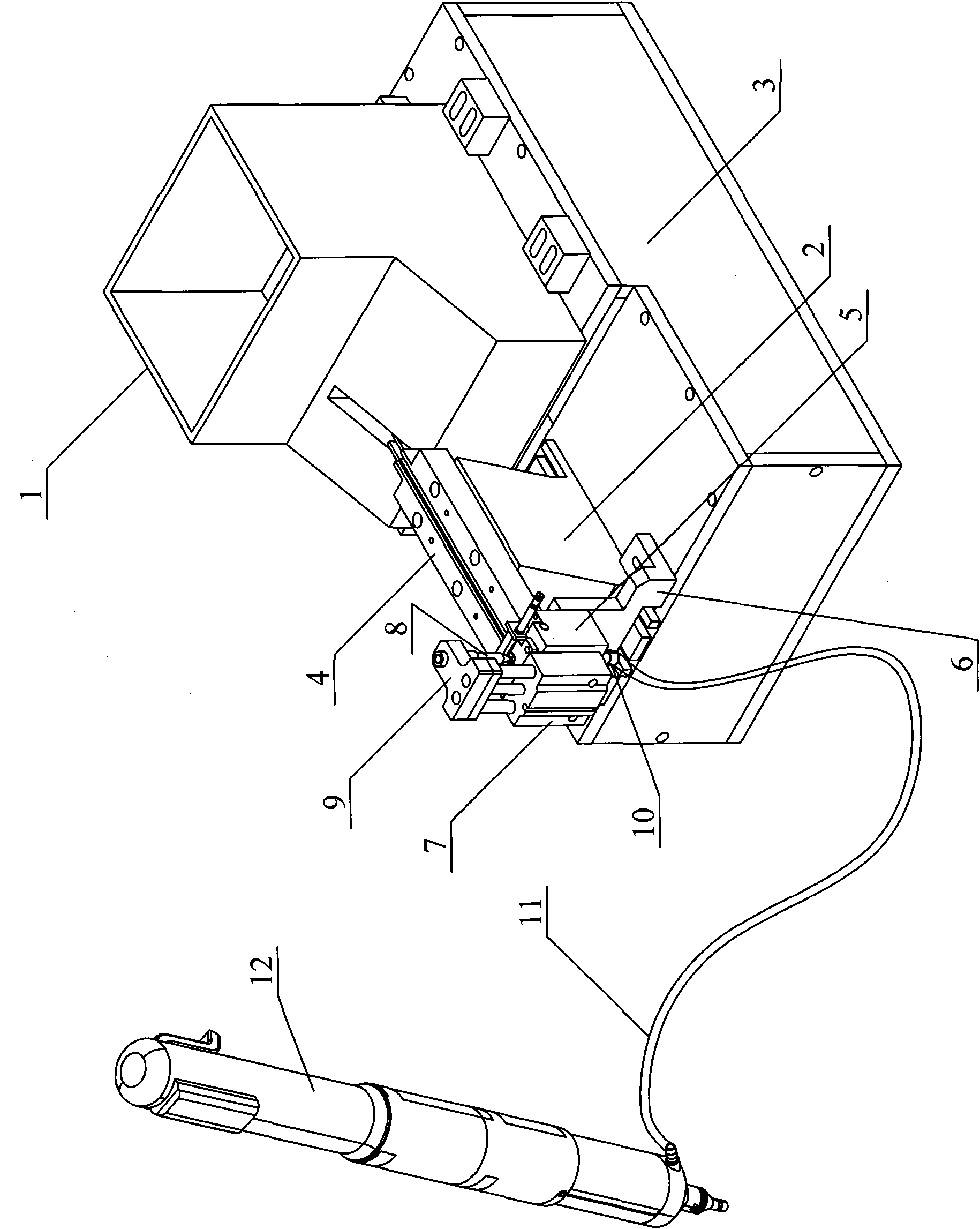
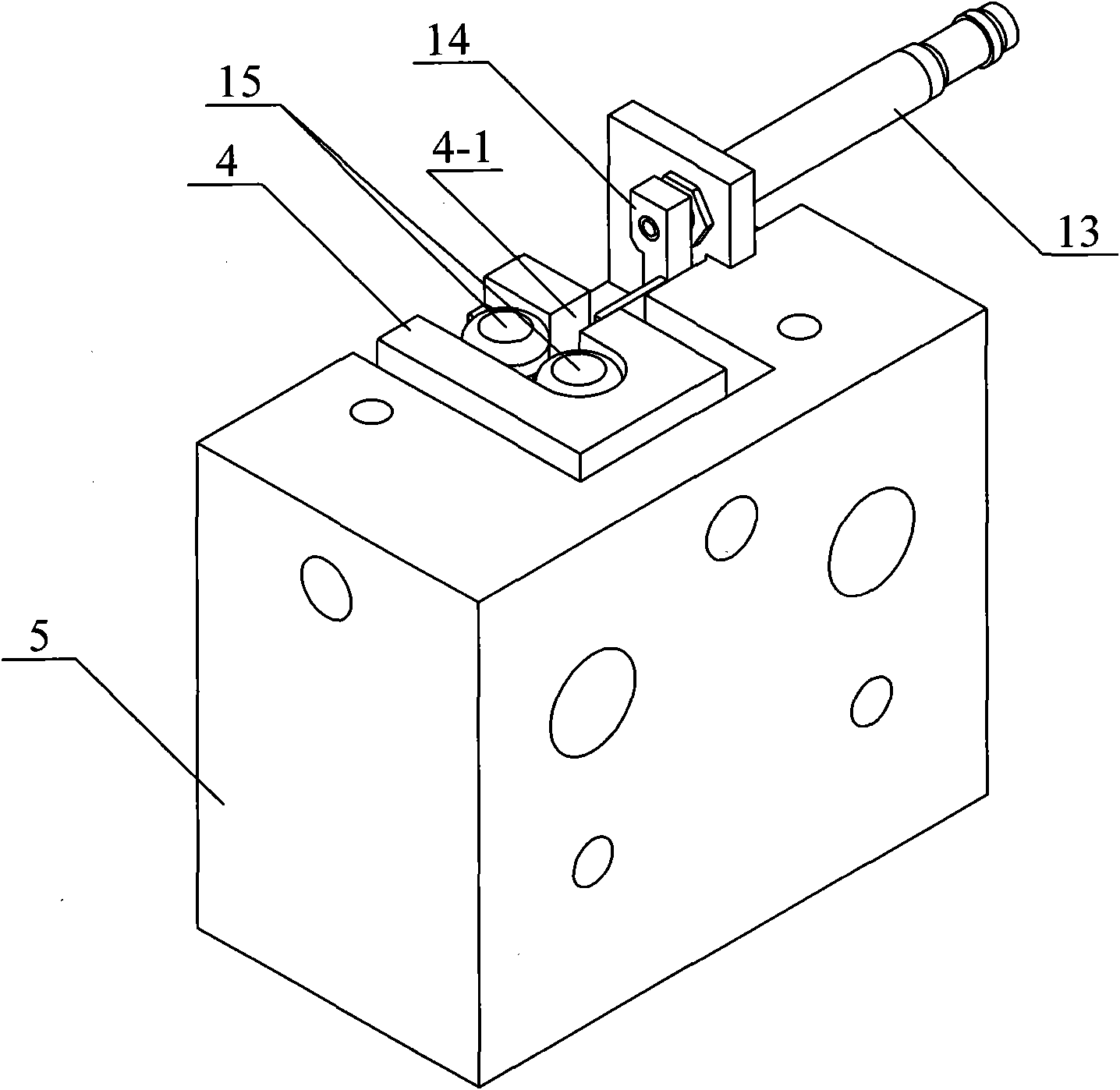
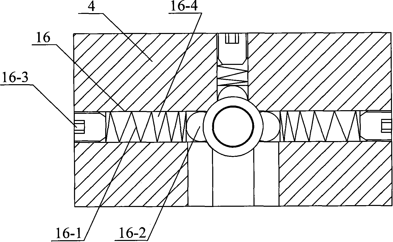
[0023] like figure 1 As shown, the screw locking machine in this embodiment includes a vibrating feeder 1, a linear vibrator 2, a main body electric control box 3, a material channel 4, a distribution block 5, a support block 6, a cylinder 7, an air blowing nozzle 8, a blowing Air nozzle fixing block 9, air guide tube connector 10, air guide tube 11 and locking mechanism 12.

[0024] The above-mentioned vibrating feeder 1 and linear vibrator 2 are connected on the main electric control box 3, and the material channel 4 is connected on the linear vibrator 2, and one end of the material channel 4 is connected with the discharge port of the vibrating feeder 1, and the other One end links to each other with distributing block 5. The distribution block 5 is connected to the electric control box 3 of the main body by means of a support block 6 . The air cylinder 7 is connected to the above-mentioned distribution block 5 , and the front end of the piston rod of the air cylinder 7 i...


PUM


Abstract

The invention discloses a screw locking machine, which is precise in alignment, convenient to operate and high in working efficiency. The screw locking machine consists of a main body electric cabinet, a feed mechanism, a distribution mechanism and a locking mechanism.

Description

technical field [0001] The invention relates to a screw locking mechanism, in particular to a screw locking machine. Background technique [0002] The existing electric screwdriver needs to manually put the screw to be locked into the threaded hole when locking the screw, or manually put the screw on the bit head for locking. This is not only inefficient, but also increases the labor intensity of the operator, which is likely to cause fatigue operation. Contents of the invention [0003] The technical problem to be solved by the present invention is to provide a screw locking machine with accurate alignment, convenient operation and high working efficiency. [0004] The invention includes a main body electric control box; a feeding mechanism, the feeding mechanism includes a vibrating feeder, a linear vibrator and a feeder, the feeder is connected to the linear vibrator, and one end of the feeder is connected to the discharge of the vibrating feeder On the mouth, the vib...

Claims


Application Information

Patent Timeline
IPC IPC(8): B25B21/02B25B23/04
Inventor 吕绍林汪炉生
Owner BOZHON PRECISION IND TECH CO LTD
Why Eureka
Try Eureka