Failure frequency sensitivity based method for arranging vibrating sensor of helicopter gearbox

A vibration sensor and fault frequency technology, which is applied in the direction of instruments, special data processing applications, electrical digital data processing, etc., can solve problems such as unsatisfactory results, high cost, and small amplitude at the location of the vibration sensor

Inactive Publication Date: 2012-01-11
BEIHANG UNIV
View PDF0 Cites 0 Cited by
  • Summary
  • Abstract
  • Description
  • Claims
  • Application Information

AI Technical Summary

Problems solved by technology

[0004] Disadvantages of the current technology: the installation position of the vibration sensor is determined based on experience, and it cannot be guaranteed that the selected installation position is the best installation position. When the operating frequency changes, the vibration amplitude at the position of the vibration sensor may suddenly decrease
However, the method of modal testing is used to determine the installation position of the vibration sensor, which is time-consuming, laborious and expensive, and because the high-order modes are difficult to excite, the results obtained often cannot meet the requirements.

Method used


Image

  • Failure frequency sensitivity based method for arranging vibrating sensor of helicopter gearbox
  • Failure frequency sensitivity based method for arranging vibrating sensor of helicopter gearbox
  • Failure frequency sensitivity based method for arranging vibrating sensor of helicopter gearbox

Examples


Embodiment

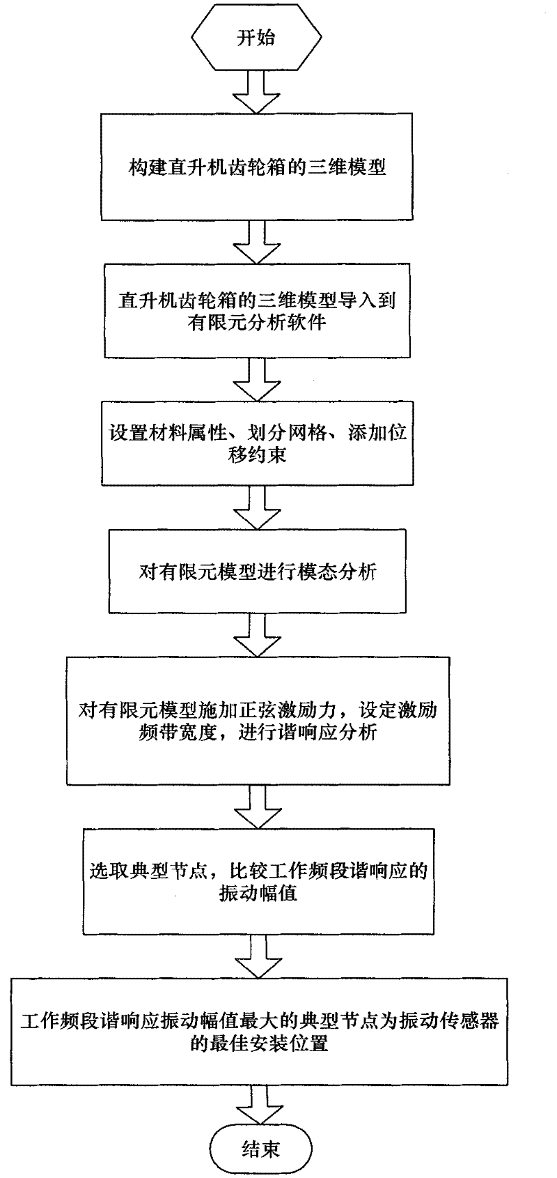
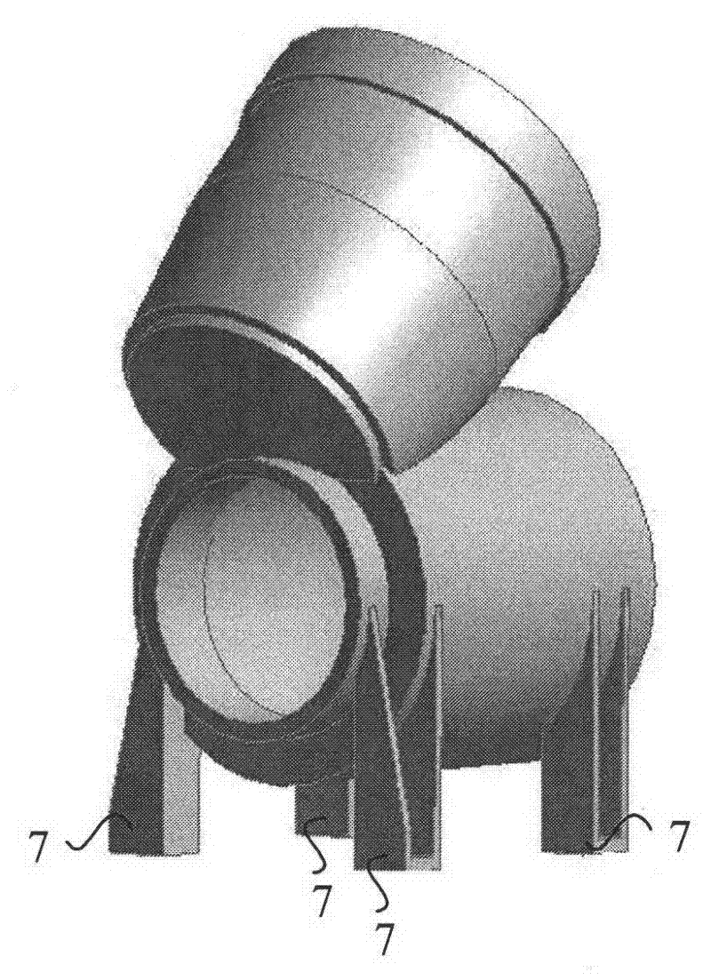
[0050] Step 1: Draw a high-precision and complete three-dimensional solid model of the gearbox of the helicopter medium reducer in ANSYS WORKBENCH. The drawn solid model of the gearbox is as follows: figure 2 shown.

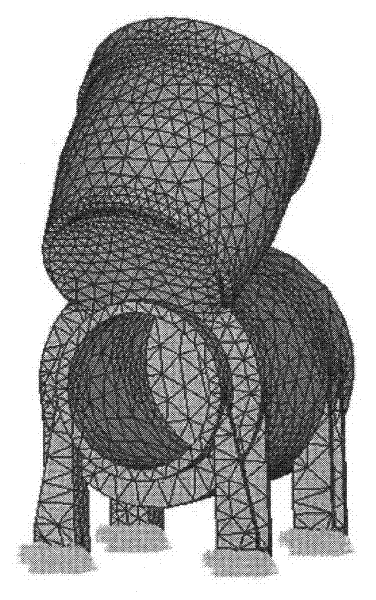
[0051] Step 2: Import the 3D solid model of the helicopter reducer gearbox drawn by ANSYS WORKBENCH into ANSYS, and set the material property density to 7850Kg / m through menu operations 3 , elastic modulus 2.0x10 11 Pa, Poisson's ratio 0.3, and divide the finite element grid, add three-dimensional zero displacement constraints to the four legs 7 of the reducer in the helicopter, divide the grid, add displacement constraints, and obtain the finite element model as follows image 3 shown.

[0052] Step 3: Carry out modal analysis on the finite element model. The modal order S is selected as 20. The first 20 modal natural frequencies of the reducer gearbox in the helicopter are shown in Table 1.

[0053] Table 1 The first 20 modal natural frequencies of the redu...


PUM


Abstract

The invention discloses a failure frequency sensitivity based method for arranging a vibrating sensor of a helicopter gearbox, comprising the following steps of: (1) constructing a three-dimensional model of the helicopter gearbox; (2) establishing a finite element model of the helicopter gearbox; (3) analyzing the modality of the finite element model of the helicopter gearbox; (4) analyzing the harmonic response of the finite element model of the helicopter gearbox; and (5) determining the installation position of the vibrating sensor of the helicopter gearbox. The invention can rapidly and precisely determine the optimum arrangement position of the vibrating sensor for the traditional gearbox, also has the directive function on reserving the installation position of the sensor for the gearbox in design, and has the important significance on fully acquiring the early failure signals of the gearbox for early failure diagnosis.

Description

technical field [0001] The invention relates to a method for determining the installation position of a vibration sensor, in particular to a method for arranging a vibration sensor of a helicopter gearbox based on fault frequency sensitivity, and belongs to the technical field of vibration fault diagnosis of a helicopter gearbox. Background technique [0002] Since 1991, when the first helicopter equipped with a certified Health&Usage Monitoring System (HUMS) came out, more and more helicopters are equipped with HUMS in various countries in the world, and the vibration sensor is the helicopter usage and monitoring system ( An important part of HUMS). At present, many literatures have no clear instructions on the installation position of the gearbox vibration sensor, but it is generally believed that the vibration sensor should be installed as close to the bearing as possible. When measuring radial vibration, the vibration sensor is generally installed on the outside of the ...

Claims


Application Information

Patent Timeline
Patent Type & Authority Patents(China)
IPC IPC(8): G06F17/50
CPCY02T90/00
Inventor 苏勋文王少萍朱冬梅石健
Owner BEIHANG UNIV
Why Eureka
Try Eureka