
Connector

A technology of connectors and contact parts, which is applied in the direction of connections, devices for preventing wrong connections, electrical components, etc. It can solve the problems of complex manufacturing process, easy deviation of protruding positions, and uniform contact pressure of difficult points, so as to prevent accidents The effect of maintaining stability in loosening and contact state

Inactive Publication Date: 2010-08-11
ALPS ALPINE CO LTD
View PDF2 Cites 7 Cited by
  • Summary
  • Abstract
  • Description
  • Claims
  • Application Information

AI Technical Summary

Problems solved by technology

Therefore, the manufacturing process is complicated, and the mutual mounting positions of multiple contacts are prone to deviation.
[0011] In particular, as described in Patent Document 2, a plurality of contacts are mounted on the socket body at short intervals, so not only the manufacturing process is complicated, but also the protruding position of each contact from the socket body is prone to deviation.
Therefore, when connecting the connector on the socket side and the connector on the plug side, it is difficult to keep the contact pressure uniform across all the contacts.

Method used


Image

  • Connector
  • Connector
  • Connector

Examples


Embodiment Construction

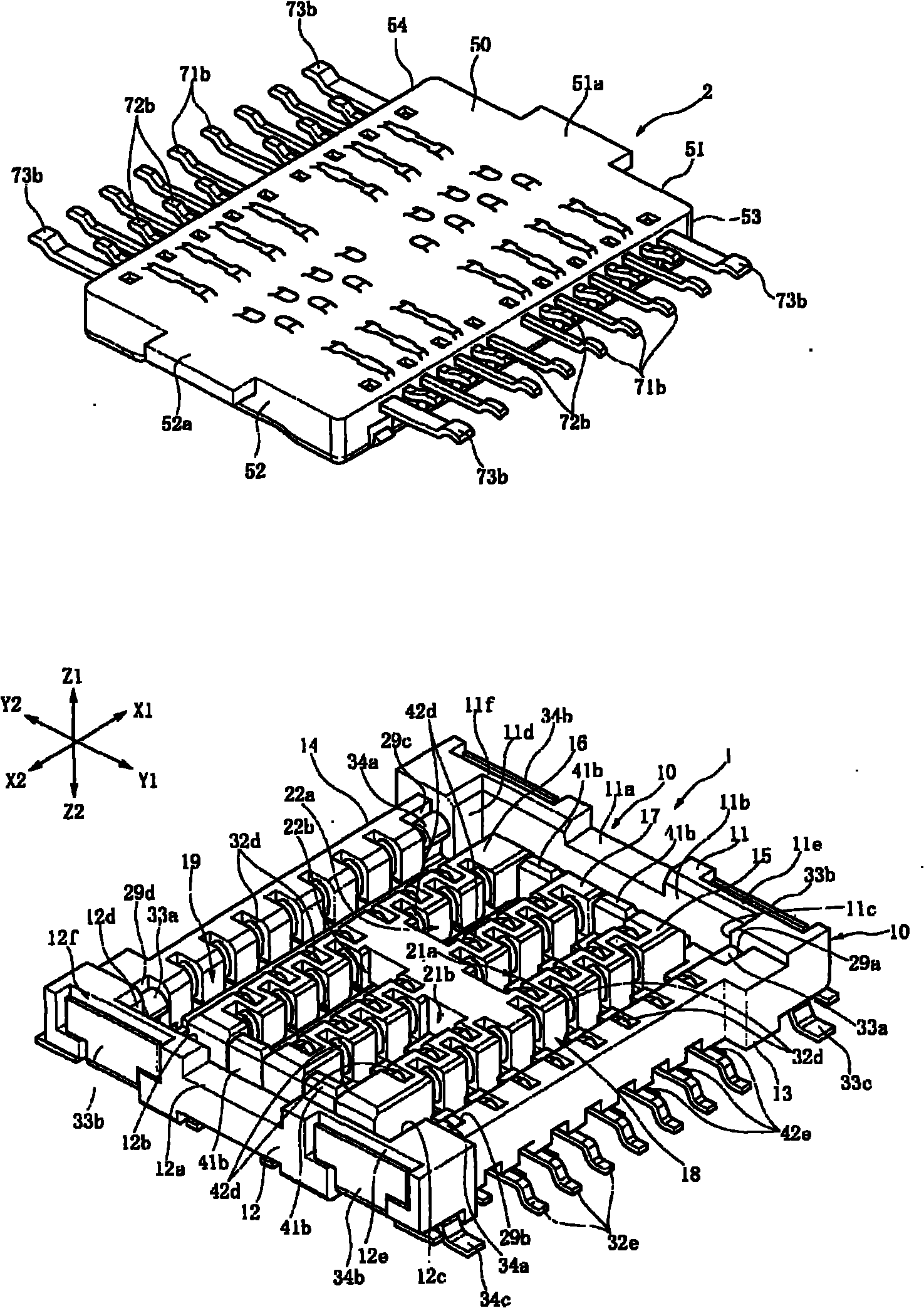
[0048] like figure 1 As shown, the connector has a connector 1 on the socket side and a connector 2 on the plug side. For example, the connector 1 on the socket side is mounted on the surface of the hard substrate, the connector 2 on the plug side is mounted on the flexible wiring board, and the connector 2 on the plug side is combined with the connector 1 on the socket side to form flexible wiring. The conduction part of the substrate and the conduction part of the hard substrate are independently conducted.

[0049] The connector 1 on the receptacle side has a receptacle main body 10 made of synthetic resin. The Z1 side (upper side) of the receptacle main body 10 is a connecting side to be coupled with the plug-side connector 2 , and the Z2 side (lower side) is a fixed side facing the board. In addition, the X1 side is the front, the X2 side is the rear, the Y1 side is the right side, and the Y2 side is the left side.

[0050] (Structure of the connector on the socket sid...


PUM


Abstract

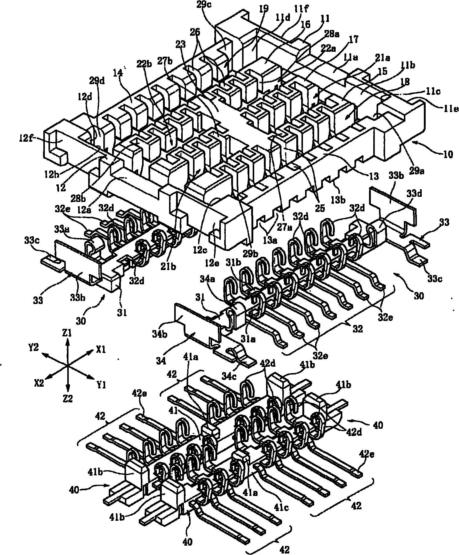
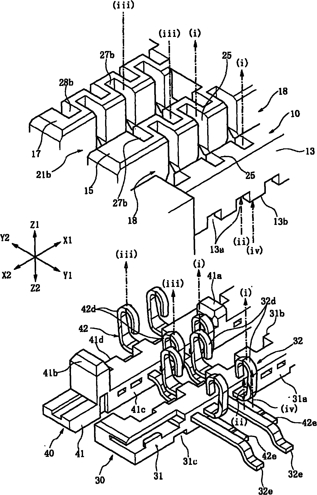
The invention provides a connector, which can precisely position all joint components and can be assembled with fewer processes under the condition of arranging a plurality of joint components on the connector aside a socket. A socket main body (10) is provided with jointing openings (18, 19, 21a, 21b, 22a, 22b). An outside socket joint component (32) is fixed on an inside joint supporter (41) which is made from synthetic resin. Through assembling an outside joint supporter (31) and the inside joint supporter (41) in the jointing openings (18, 19, 21a, 21b, 22a, 22b), the positioning is more precise and a contact part (32d) of the outside socket joint component (32) and the contact part (42d) of an inside socket joint component (42) can be precisely assembled.

Description

technical field [0001] The present invention relates to a socket-side connector combined with a plug body, and more particularly to a connector capable of positioning and attaching a plurality of socket contact members to the socket body with high precision. Background technique [0002] Thin connectors are used to electrically connect a plurality of current conducting portions formed on a printed wiring board and a plurality of current conducting portions formed on another printed wiring board or the like. This connector has a receptacle-side connector that conducts with the conduction portion of one substrate, and a plug-side connector that conducts with the conduction portion of the other substrate. [0003] In the connector described in the following Patent Document 1, a plug insertion recessed portion is formed on the main body of the receptacle side in the coupling direction with the plug side, and a plurality of contacts are further formed at intervals in the plug ins...

Claims


Application Information

Patent Timeline
IPC IPC(8): H01R13/64H01R12/00H01R12/71H01R12/78H01R12/79
Inventor 伊藤正志横田纯一郎我妻透
Owner ALPS ALPINE CO LTD
Learn More