Parking brake modulator and use of a brake modulator as a parking brake modulator

A regulator and brake technology, applied in the direction of brakes, brake transmission devices, automatic starting devices, etc., can solve problems such as increased fuel consumption, achieve the effect of preventing lock-up and improving safety

Active Publication Date: 2010-08-11
ZF CV SYST EURO BV
View PDF0 Cites 4 Cited by
  • Summary
  • Abstract
  • Description
  • Claims
  • Application Information

AI Technical Summary

Problems solved by technology

This in turn leads to an increase in the fuel c

Method used


Image

  • Parking brake modulator and use of a brake modulator as a parking brake modulator
  • Parking brake modulator and use of a brake modulator as a parking brake modulator
  • Parking brake modulator and use of a brake modulator as a parking brake modulator

Examples


Embodiment Construction

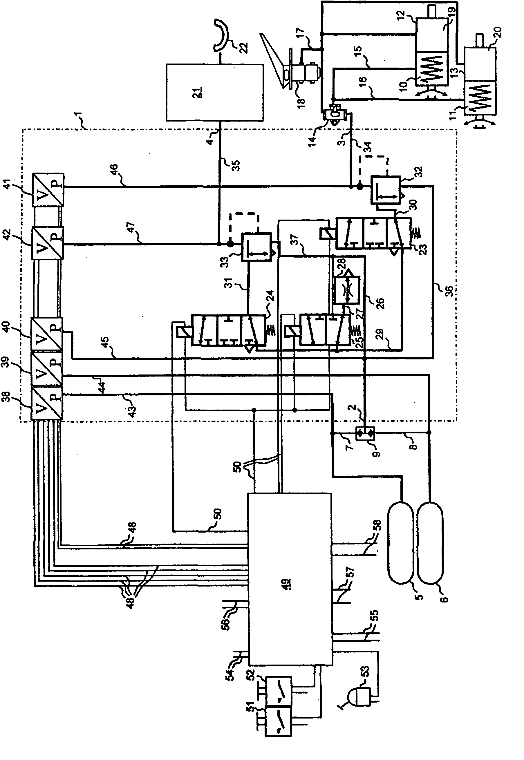
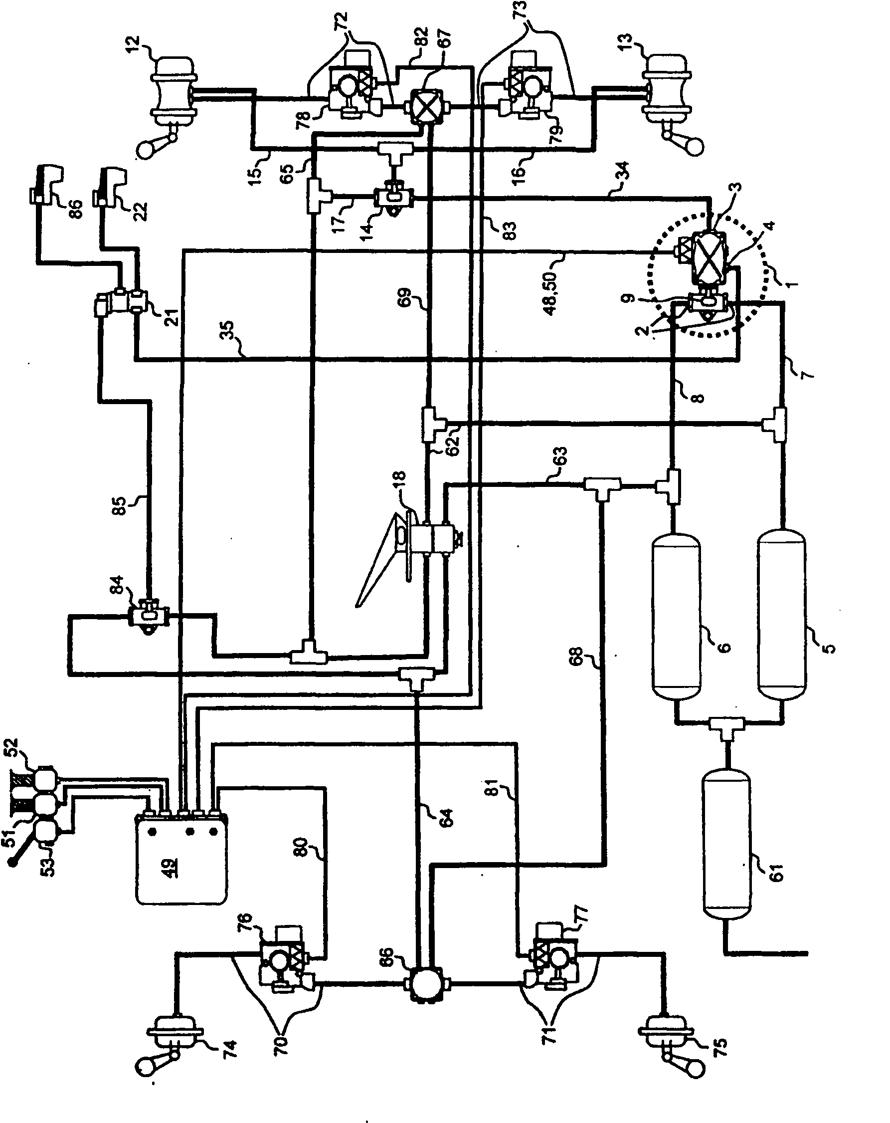
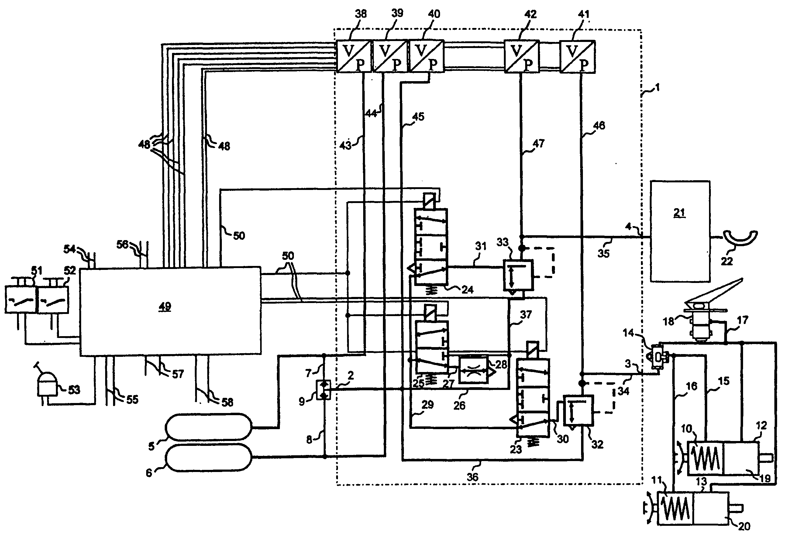
[0041] figure 1 A part of a braking system for a combined vehicle consisting of a tractor and at least one trailer is schematically shown. In this case, the drawing shows in particular a parking brake regulator 1 together with other components of the brake system, with which the parking brake function for the tractor brake and the parking brake for the trailer brake are provided. move function.

[0042]The parking brake regulator 1 has a compressed air inlet 2 , a first compressed air outlet 3 and a second compressed air outlet 4 . The parking brake regulator 1 is supplied with compressed air from the first compressed air storage container 5 and / or from the second compressed air storage container 6 via the compressed air inlet 2 . In this case, the first compressed air storage container 5 is firstly connected via the compressed air line 7 to the double non-return valve 9 and the second compressed air storage container 6 is connected via the compressed air line 8 to the doubl...


PUM


Abstract

The invention relates to a parking brake modulator (1) for controlling a parking brake mode of brakes of a vehicle, to the use of a brake modulator as a parking brake modulator (1) and to a brake system comprising said parking brake modulator (1). The parking brake modulator (1) comprises at least one compressed air inlet (2) via which compressed air is supplied to the parking brake modulator (1). The parking brake modulator (1) further comprises at least one electromagnetically operated valve element (23), a second electromagnetically operated valve element (24) and a third electromagnetically operated valve element (25). A pneumatic pressure in a compressed air line (30, 34) can be controlled via the first valve element (23) and is made available at a first compressed air outlet (3) of the parking brake modulator (1). A pneumatic pressure in a compressed air line (31, 35) can be controlled via the second valve element (24) and is made available at a second compressed air outlet (4) of the parking brake modulator (1). In the non-energized state of the first valve element (23) and in the non-energized state of the second valve element (24), the first compressed air line (30, 34) can be bled via the first valve element (23) and the second compressed air line (31, 35) can be bled via the second valve element (24). When the first valve element (23) is non-energized and the second valve element (24) is non-energized, too, while the third valve element (25) is energized, the first compressed air line (30) can be bled via the first valve element (23) and the second compressed air line (31) can be bled via the second valve element (24).

Description

technical field [0001] The invention relates to a parking brake regulator for controlling the parking brake function of a vehicle brake according to the preamble of claim 1 and to a brake regulator for an electronic brake system according to claim 13 Application as a parking brake regulator. Background technique [0002] The parking brake regulator is used to control at least one pneumatic pressure in order to control the parking brake function of the brakes of the vehicle. In a conventional design, the parking brake regulator provides two control pressures. For this purpose, the parking brake regulator has a first compressed air line leading to the first compressed air outlet and a second compressed air line leading to the second compressed air outlet. Furthermore, the known parking brake regulator has a first and a second valve arrangement which are each electrically controllable and electromagnetically actuatable. In the de-energized first and second valve arrangements...

Claims


Application Information

Patent Timeline
IPC IPC(8): B60T7/20B60T13/68
CPCB60T7/20B60T13/683
Inventor 亨宁·弗尔斯特哈特穆特·罗森达尔沃尔夫冈·施特拉赫
Owner ZF CV SYST EURO BV
Why Eureka
Try Eureka