Filter

A technology of filters and filter holes, which can be used in home appliances, applications, kitchen utensils, etc., and can solve problems such as unseen, clogged, and dangerous

Inactive Publication Date: 2010-08-18
CHANGSHU KASMAIN
View PDF5 Cites 0 Cited by
  • Summary
  • Abstract
  • Description
  • Claims
  • Application Information

AI Technical Summary

Problems solved by technology

The operation method in the prior art usually moves the pot cover artificially, so that a gap is formed between the pot cover and the open part of the pot body, and the soup (also called soup) flows out from the gap. It works, but there are at least the following disadvantages: First, it is difficult to grasp the size of the gap. If the gap is too narrow, it will affect the efficiency of decanting the soup on the one hand, and on the other hand, it is easy to appear from the small solid matter in the pot. Blocking the gap will lead to the failure of decanting, and if the gap is too large, then the solids that should have stayed in the pot will escape with the soup, which not only reduces the quality of the soup, but also is dangerous, because Once the larger solids come out of the pot with the soup, it will cause splashing and hurt the operator's limbs such as hands; the second is that the operation efficiency is low, because the channel for the soup to decant out of the pot only depends on the only gap , in the decanting process, the waiting time is long; the third is dangerous, because in the process of operation (decanting juice), it is difficult for the operator's hands to effectively control the pot cover, and the pot cover often appears to swim, and even The lid of the pot is turned over, and there is a risk that the operator's hands will directly contact hot materials such as dishes, etc.
For this reason, the applicant has searched, yet, in disclosed domestic and foreign patents and non-patent literature, there is no relevant technical suggestion, and the above listed but not limited to the above listed such as hotels, restaurants, Canteens and households are in urgent need of a filter to complete the juice filtration, that is, to complete the solid-liquid separation

Method used


Image

  • Filter
  • Filter
  • Filter

Examples


Embodiment Construction

[0019] In order to enable the examiners of the patent office, especially the public, to understand the technical essence and beneficial effects of the present invention more clearly, the applicant will describe in detail below in conjunction with the accompanying drawings in the form of embodiments, but none of the descriptions of the embodiments is a description of the present invention. Restriction of the inventive solution, any equivalent transformation made according to the concept of the present invention which is only in form but not in substance shall be regarded as the scope of the technical solution of the present invention.

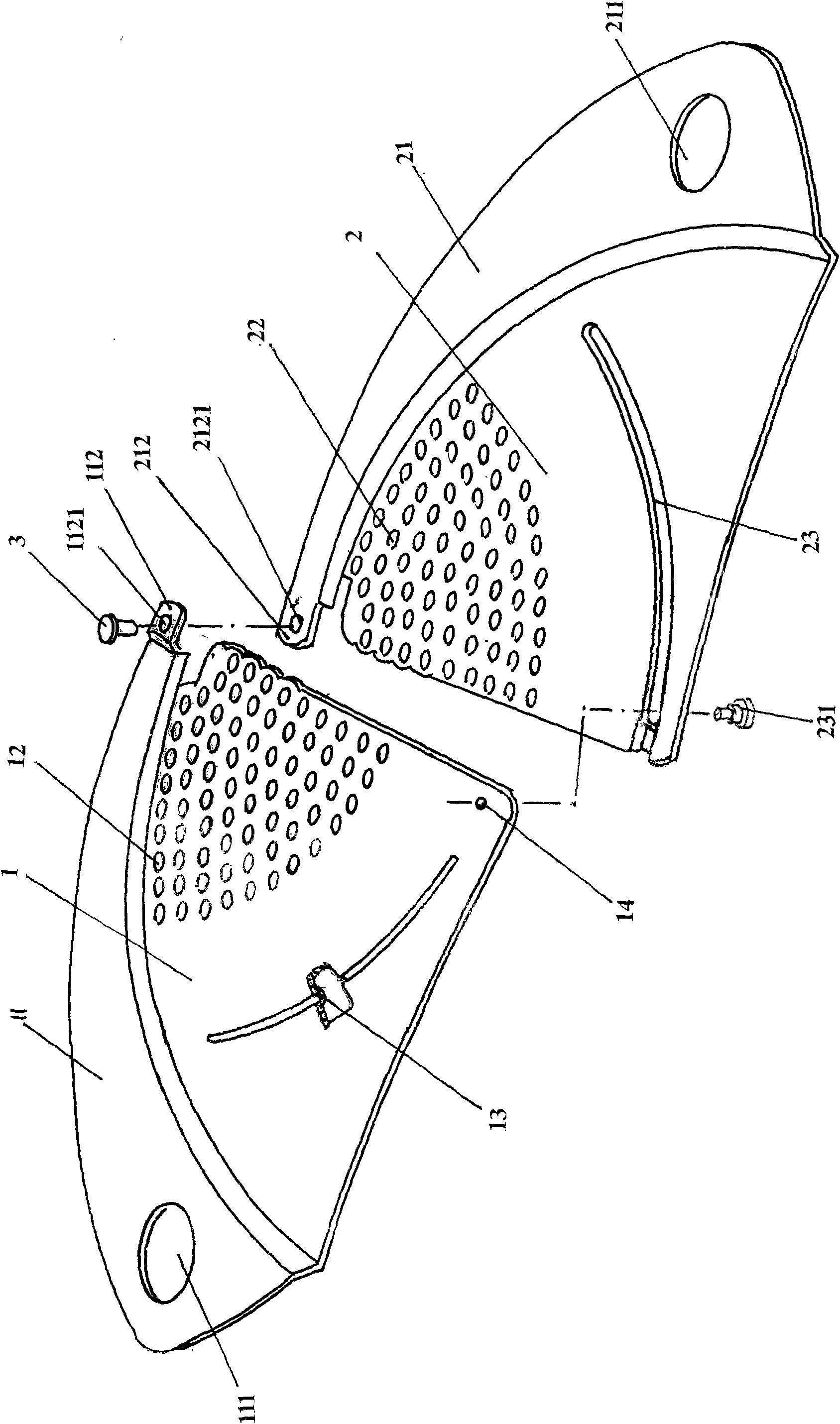
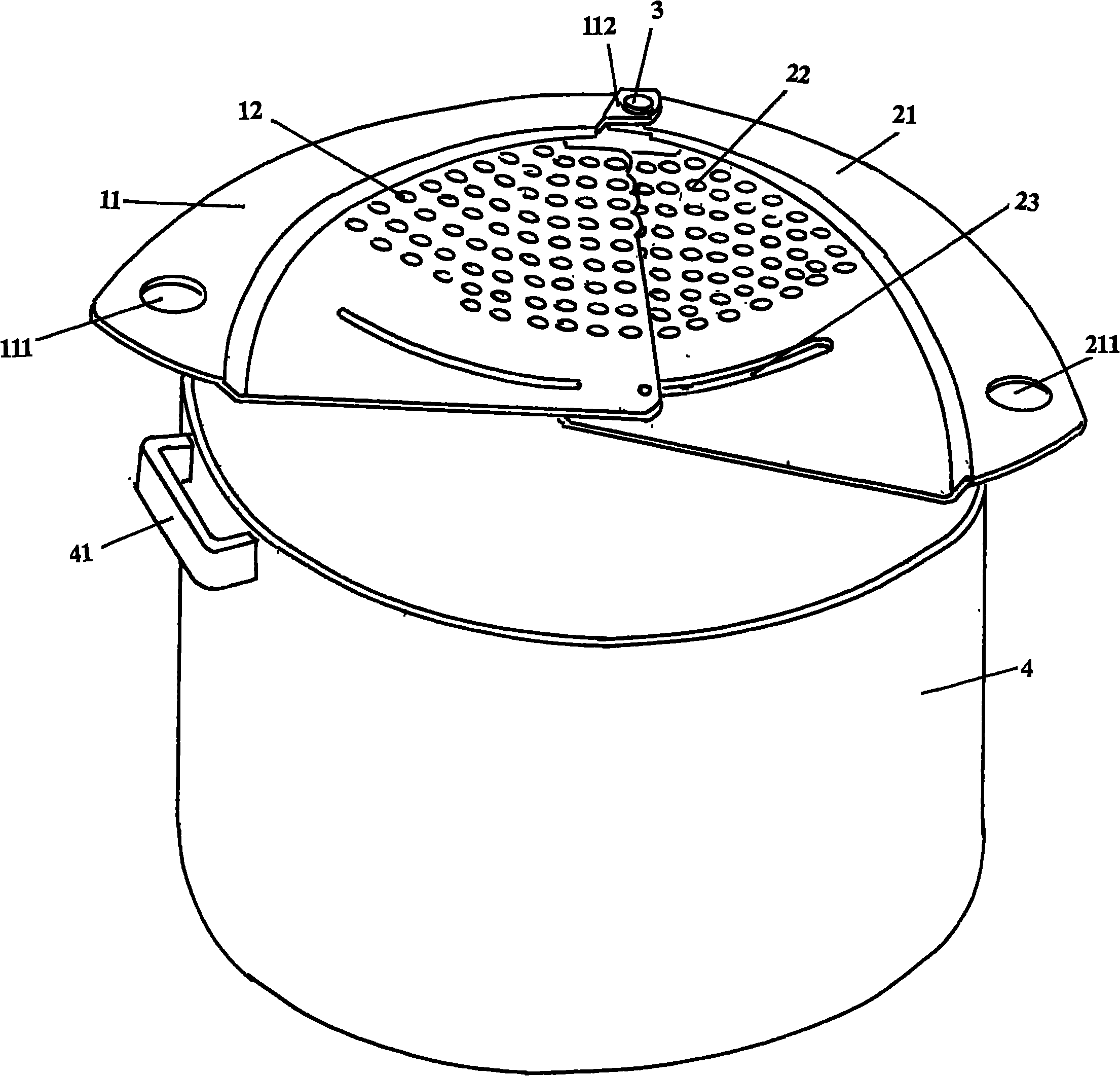
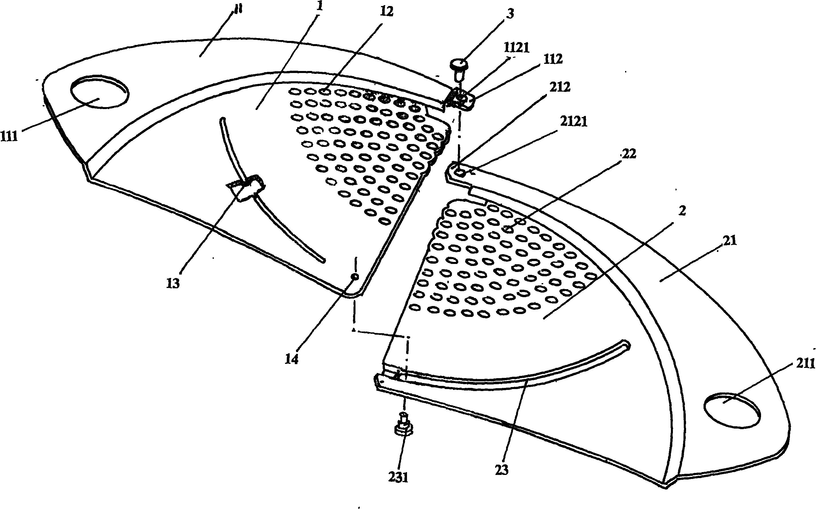
[0020] Please see figure 1 , the first and second filter lobes 1 and 2 with the same overall shape and size are provided, more specifically, the first and second filter lobes 1 and 2 are provided with fan-shaped or triangular shapes. The outer edge of the first filter lobe 1 or the outside constitutes a first step edge 11, the shape of the first...


PUM


Abstract

The invention relates to a filter belonging to the technical field of cooking appliances. The filter comprises a first filter valve with a first step edge and a second filter valve with a second step edge, wherein one end of the first step edge is provided with a first finger hole, the other end is provided with a first hinged ear, one end of the second step edge is provided with a second finger hole, and the other end is provided with a second hinged ear which is hinged on the first hinged ear. The first filter valve is provided with a first filter hole, the second filter valve is provided with a second filter hole, a guided sliding flange is also formed on the first filter valve, and a guided sliding flange channel is formed on the second filter valve, matched with the guided sliding flange, and internally provided with a guided sliding piece which extends out of the guided sliding flange channel and is connected with the first filter valve. The invention has the advantages of rapid soup outflow from the first filter hole and the second filter hole in a pot, safety, no pot size restriction, simple structure, convenient dismounting and mounting and capability of manual operation in the dismounting and mounting process without relying on any tool.

Description

technical field [0001] The invention belongs to the technical field of cooking utensils, and in particular relates to a filter for filtering out soup liquid in a cooking container such as a pot. Background technique [0002] People often encounter the situation of solid-liquid separation during daily cooking and even catering, such as keeping the solid in a container such as a pot, and pouring out the soup. The operation method in the prior art usually moves the pot cover artificially, so that a gap is formed between the pot cover and the open part of the pot body, and the soup (also called soup) flows out from the gap. It works, but there are at least the following disadvantages: First, it is difficult to grasp the size of the gap. If the gap is too narrow, it will affect the efficiency of decanting the soup on the one hand, and on the other hand, it is easy to appear from the small solid matter in the pot. Blocking the gap will lead to the failure of decanting, and if the...

Claims


Application Information

Patent Timeline
Patent Type & Authority Applications(China)
IPC IPC(8): A47J43/28
Inventor 金钟文
Owner CHANGSHU KASMAIN
Why Eureka
Try Eureka