
Hydraulic split block structure positioning clamp of free curve surface work pieces

A surface workpiece and structure positioning technology, applied in workpiece clamping devices, manufacturing tools, etc., can solve problems such as increasing the cost of free-form surface workpieces, increasing the cycle of processing or measurement, and affecting work efficiency, achieving a high degree of automation and versatility. Good, improve the effect of positioning accuracy

Inactive Publication Date: 2010-08-18
XIAMEN UNIV
View PDF1 Cites 8 Cited by
  • Summary
  • Abstract
  • Description
  • Claims
  • Application Information

AI Technical Summary

Problems solved by technology

[0002] At present, when processing or measuring free-form surface workpieces, it is necessary to develop and design different positioning fixtures for free-form surface workpieces of different shapes or sizes, which not only increases the cost of free-form surface workpiece processing or measurement, but also increases the processing or measurement cycle. , which in turn affects its overall work efficiency, so it has a certain impact on processing or measurement work

Method used


Image

  • Hydraulic split block structure positioning clamp of free curve surface work pieces
  • Hydraulic split block structure positioning clamp of free curve surface work pieces
  • Hydraulic split block structure positioning clamp of free curve surface work pieces

Examples


Embodiment Construction

[0024] The present invention will be further described below in conjunction with the accompanying drawings.

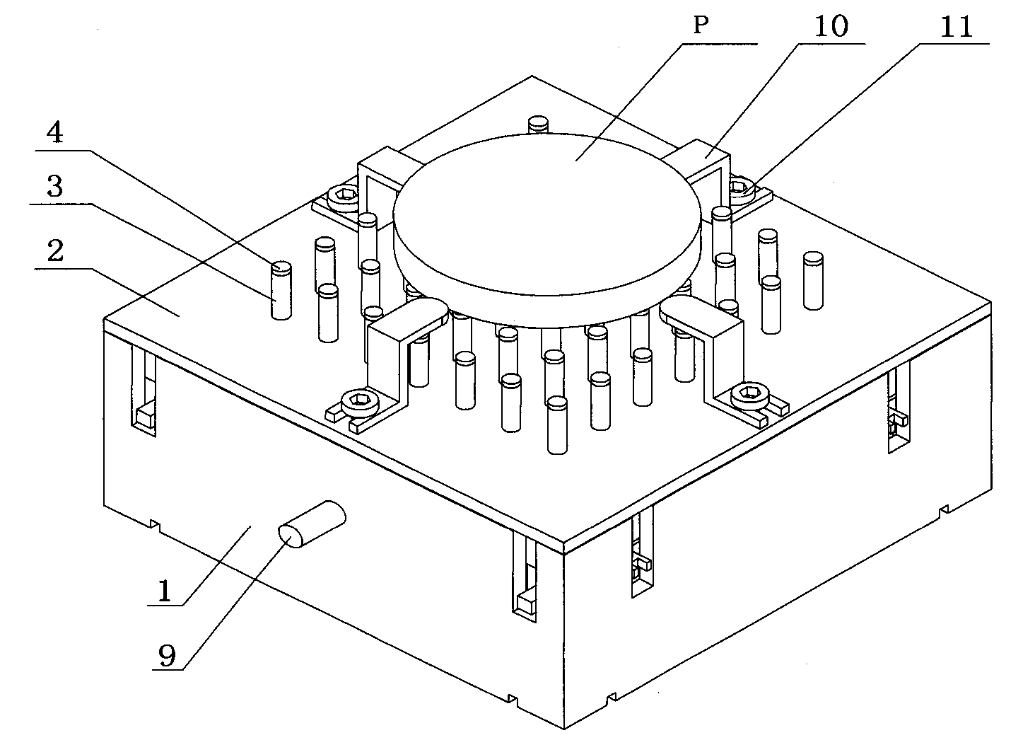
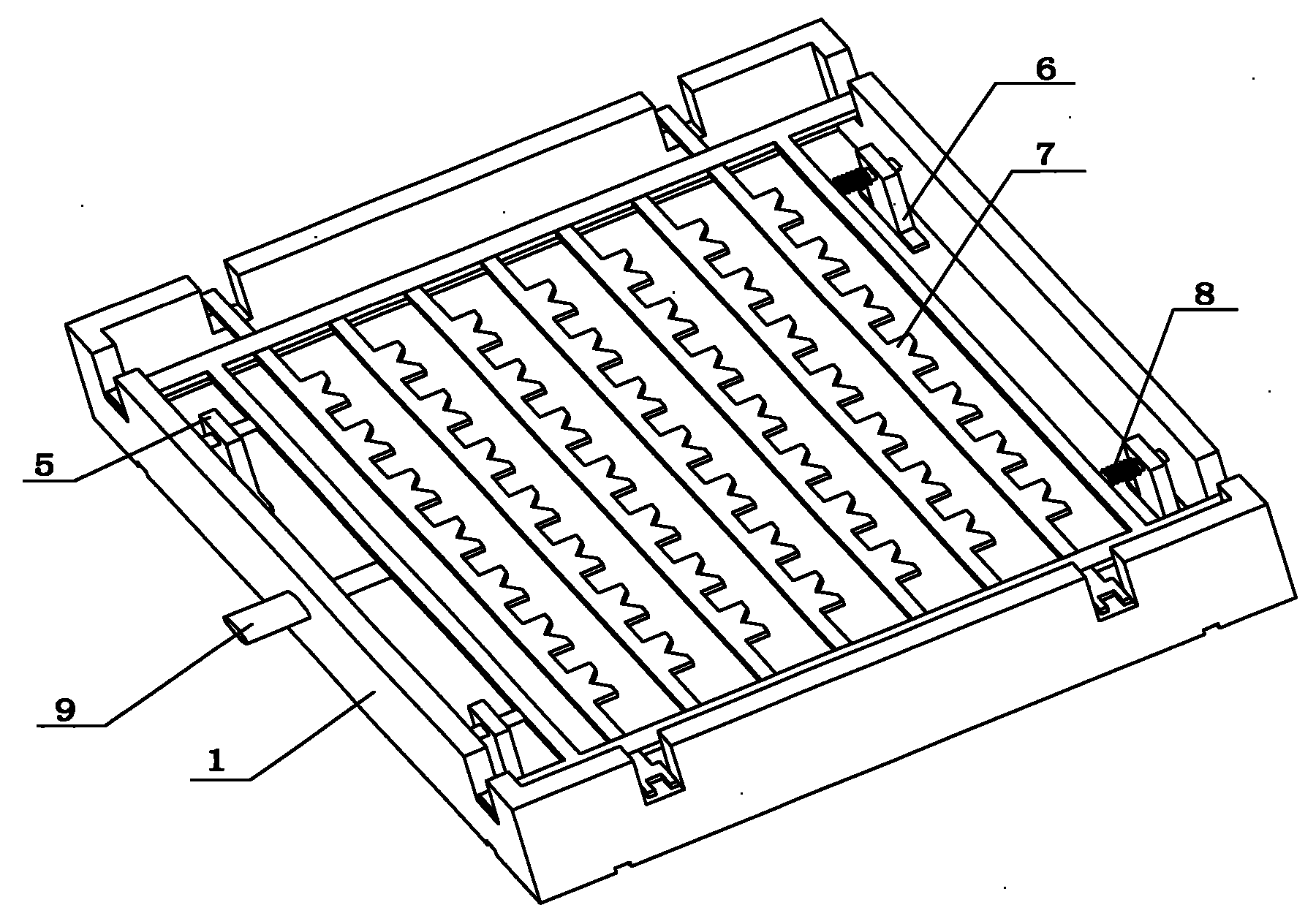
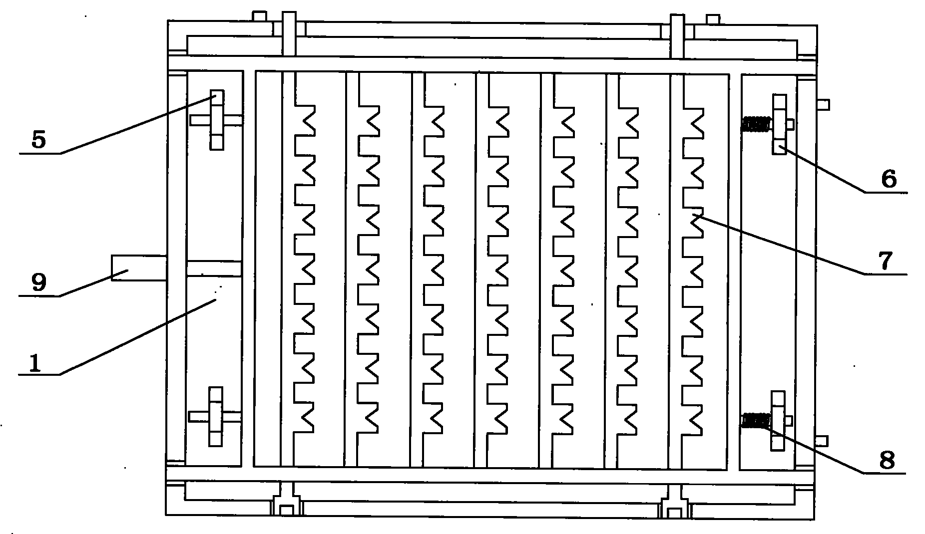
[0025] see Figure 1~3 , 10 and 11, the embodiment of the present invention is provided with base 1, upper cover plate 2, one-way hydraulic cylinder 3, piezoelectric ceramics 4, left bracket 5, right bracket 6, hydraulic cylinder clamping frame 7, return spring 8, lock Tight hydraulic cylinder 9, fixed top block 10, screw 11, oil cylinder 12, filter 13, oil pump 14, throttle valve 15, relief valve 16 and reversing valve 17. Among them, the upper cover plate 2 is covered on the base 1, one end of the one-way hydraulic cylinder 3 is installed on the base 1, and one end passes through the upper cover plate 2 to expose outside and paste piezoelectric ceramics 4; oil cylinder 12, filter 13, oil pump 14 , throttle valve 15, overflow valve 16 and one-way hydraulic cylinder 3 form a hydraulic circuit for controlling the movement of one-way hydraulic cylinder 3; left bracket 5...


PUM


Abstract

The invention provides a hydraulic split block structure positioning clamp of free curve surface work pieces, which relates to a positioning clamp. The hydraulic split block structure positioning clamp comprises a base, an upper cover plate, a one-way hydraulic cylinder, piezoelectric ceramics, a left support frame, a right support frame, a hydraulic cylinder clamping frame, a reset spring, a locking hydraulic cylinder, a fixed top block, an oil cylinder, a filter, an oil pump, a throttle valve, an overflow valve and a reverse valve, wherein the upper cover plate is covered on the base, one end of the one-way hydraulic cylinder is arranged on the base, the other end of the one-way hydraulic cylinder passes through the upper cover plate and is glued with the piezoelectric ceramics, the oil cylinder, the filter, the oil pump, the throttle valve, the overflow valve and the one-way hydraulic valve form a hydraulic loop, the left support frame and the right support frame are fixed on the base, the hydraulic cylinder clamping frame is arranged in the left support frame and the right support frame, the locking hydraulic cylinder is arranged on the base, the oil cylinder, the filter, the oil pump, the throttle valve, the overflow valve, the reverse valve and the locking hydraulic cylinder form the other hydraulic loop, the reset spring is arranged between the hydraulic cylinder clamping frame and the right support frame, and the fixed top plate is arranged on the upper cover plate. The invention has the advantages of good universality, larger installing and clamping dimension, high positioning precision and high automation degree.

Description

technical field [0001] The invention relates to a positioning fixture, in particular to a hydraulic positioning fixture with block structure for free-form surface workpieces. Background technique [0002] At present, when processing or measuring free-form surface workpieces, it is necessary to develop and design different positioning fixtures for free-form surface workpieces of different shapes or sizes, which not only increases the cost of free-form surface workpiece processing or measurement, but also increases the processing or measurement cycle. , which in turn affects its overall work efficiency, so it has a certain impact on processing or measurement work. [0003] Chinese Utility Model Patent Application No. 02241292.1 discloses an optical component holder for carrying an optical component, including a first ring body, a second ring body and at least three brackets. Wherein, the outer side of the second ring body is adjacent to the inner side of the first ring body, ...

Claims


Application Information

Patent Timeline
Patent Type & Authority Applications(China)
IPC IPC(8): B25B11/00
Inventor 郭隐彪柯晓龙
Owner XIAMEN UNIV
Learn More