Walking-beam conveyor

A technology of lifting beams and conveyors, applied in the directions of conveyors, transportation and packaging, can solve problems such as overloading of lifting beams, and achieve the effect of low cost and simple method.

Inactive Publication Date: 2010-08-18
SIEMAG
View PDF6 Cites 9 Cited by
  • Summary
  • Abstract
  • Description
  • Claims
  • Application Information

AI Technical Summary

Problems solved by technology

In the case of an increased total load to be transported cyclically, the solution of coupling several independent lifting beams must be adopted because the individual components of the lifting

Method used


Image

  • Walking-beam conveyor
  • Walking-beam conveyor
  • Walking-beam conveyor

Examples


Embodiment Construction

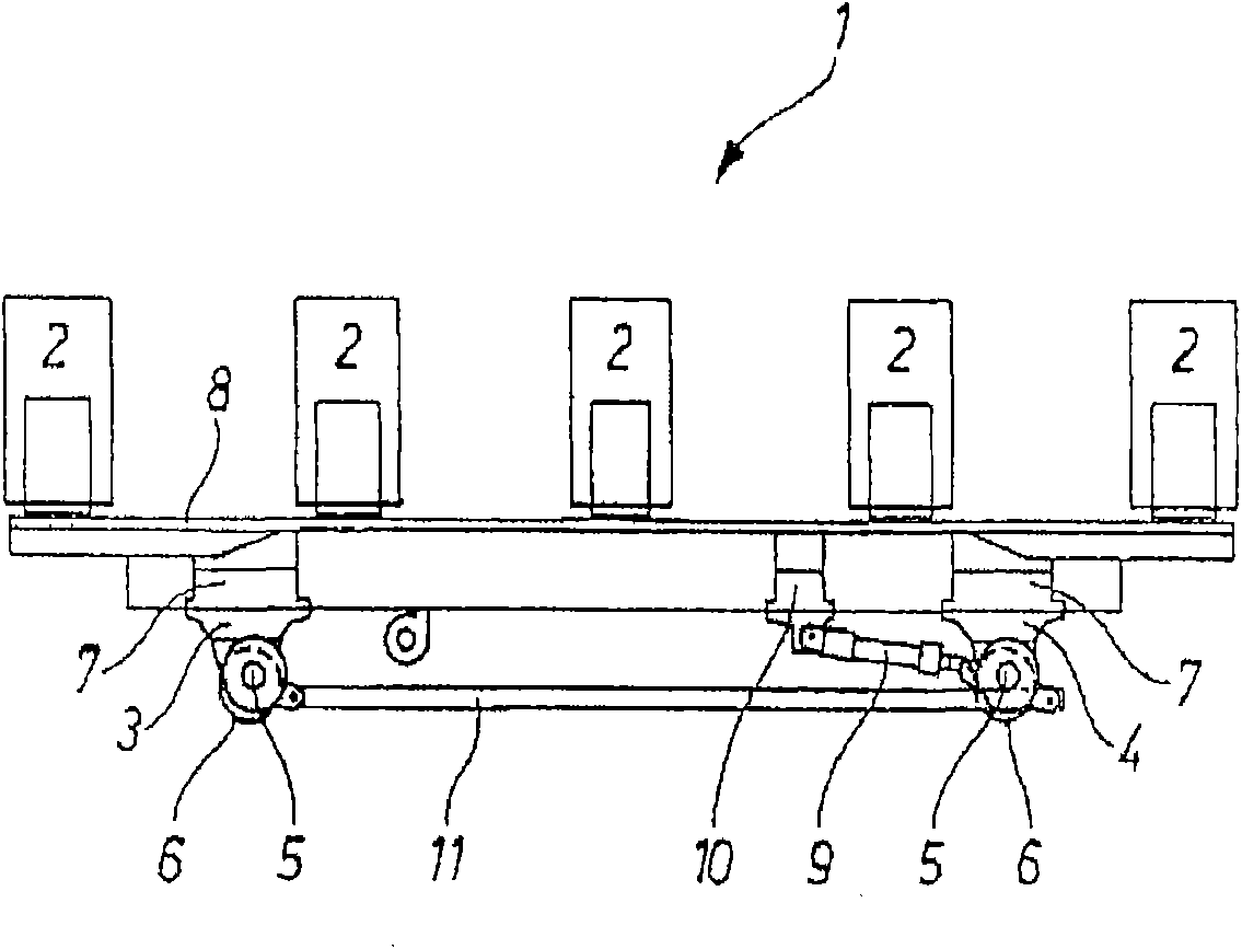
[0043] figure 1 Shown is a conventional lifting beam 1 on a conveyor line for periodically conveying (shown here) five coils or coils 2 .

[0044] The lifting beam 1 is a continuous conveyor that conveys the coils 2 placed at fixed intervals through the superposition of vertical movement and horizontal movement.

[0045] The traveling mechanism of lifting beam 1 is made of two sub-frames 3, 4, and these two sub-frames are respectively equipped with a shaft 5 and a plurality of rollers 6 connected on the shaft. When the lifting beam 1 moves horizontally or conveys, the rollers 6 move on the guide rails of the rail system inside the conveying equipment.

[0046] Each of the two sub-frames 3,4 is arranged with a lifting device 7 for lifting the crossbeam 8 carrying the coiled material 2. As an alternative and optional solution, it is also possible to pass the eccentric structure built in the sub-frames 3,4. Lifting mechanism is used to facilitate this vertical movement, and the...


PUM


Abstract

A walking-beam conveyor for stepped transport of heavy objects has an upstream beam extending in a horizontal transport direction and adapted to carry a plurality of the objects. A pair of horizontally spaced upstream supports underneath the upstream beam are associated with respective vertical and horizontal upstream drives for raising the upstream beam relative to the supports, shifting the upstream beam a step downstream, lowering the upstream beam, and shifting the upstream beam a step upstream to shift the objects on the upstream downstream in steps. In accordance with the invention a downstream beam immediately downstream of the upstream beam has an upstream end juxtaposed with a downstream end of the upstream beam with a single downstream support under the downstream beam. A pivot connects the downstream end of the upstream beam to the upstream end of the downstream beam for joint synchronous vertical and horizontal movement of the two beams.

Description

technical field [0001] The invention relates to a lifting beam conveyor for periodically conveying coils of belt or plate, stacks of plates or similar goods. Background technique [0002] Such a lifting beam conveyor has a plurality of lifting beams of the same conveyor type arranged consecutively in the conveying direction and coupled to each other as disclosed in DE 601 10 678 T2, which are periodically reciprocated together by means of their travel drives sports. The single conveyors are respectively coupled to each other through a connecting rod. Among them, one or more lifting beams can be lifted and lowered by their lifting devices, so that the coils (usually also called "coils") or similar objects placed on the transverse support surface can move periodically along the conveying direction or step by step. move. [0003] The lifting beam conveyor disclosed in DE 12 94 281 C2 is provided with a plurality of successively arranged lifting beams, wherein the couplings f...

Claims


Application Information

Patent Timeline
IPC IPC(8): B65G25/00B21C47/24
CPCB65G25/02
Inventor 卡尔·罗伯特·霍夫曼班尔德·布登班德尔
Owner SIEMAG
Why Eureka
Try Eureka