Bearing and sliding device for stretching and positioning in formwork engineering

A formwork engineering and sliding device technology, which is applied in the treatment of formwork, the preparation of building components on site, and construction, etc., can solve the problems of operation efficiency limitation, difficulty in disassembly and assembly of large formwork, etc., and achieve the effect of improving construction efficiency.

Inactive Publication Date: 2010-08-18
BEIJING ACAD OF BUILDING ENG
View PDF6 Cites 0 Cited by
  • Summary
  • Abstract
  • Description
  • Claims
  • Application Information

AI Technical Summary

Problems solved by technology

However, the existing formwork trolley can only move along the track direction during operation and cannot engage in lateral movement in the direction of formwork disassembly and assembly. Therefore, it will be very difficult to disassemble and assemble large formwork, and the improvement of operating efficiency is limited.

Method used


Image

  • Bearing and sliding device for stretching and positioning in formwork engineering
  • Bearing and sliding device for stretching and positioning in formwork engineering
  • Bearing and sliding device for stretching and positioning in formwork engineering

Examples


Embodiment Construction

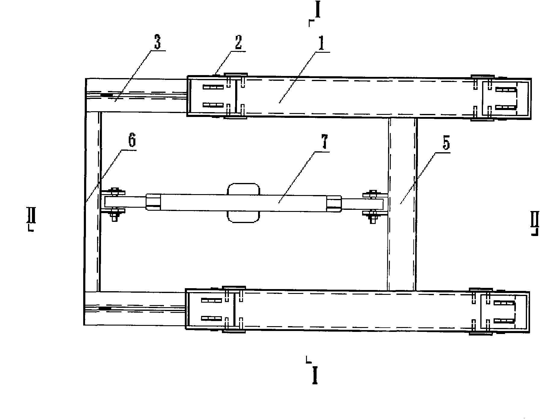
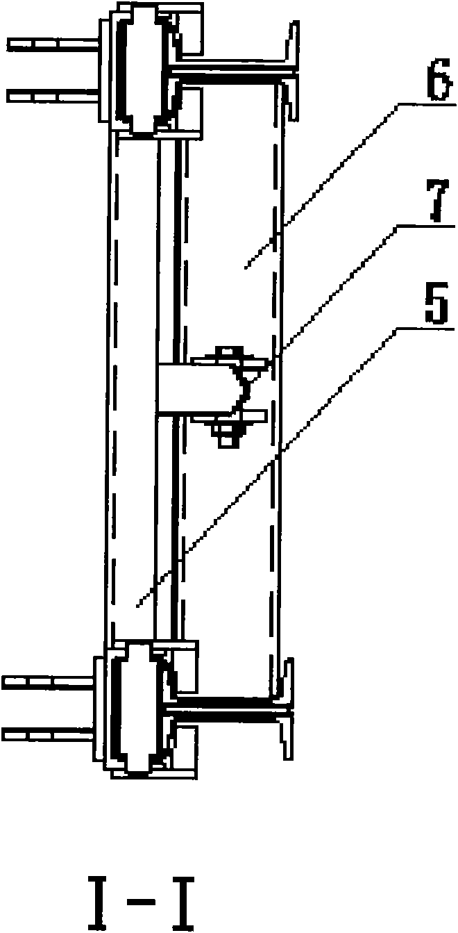
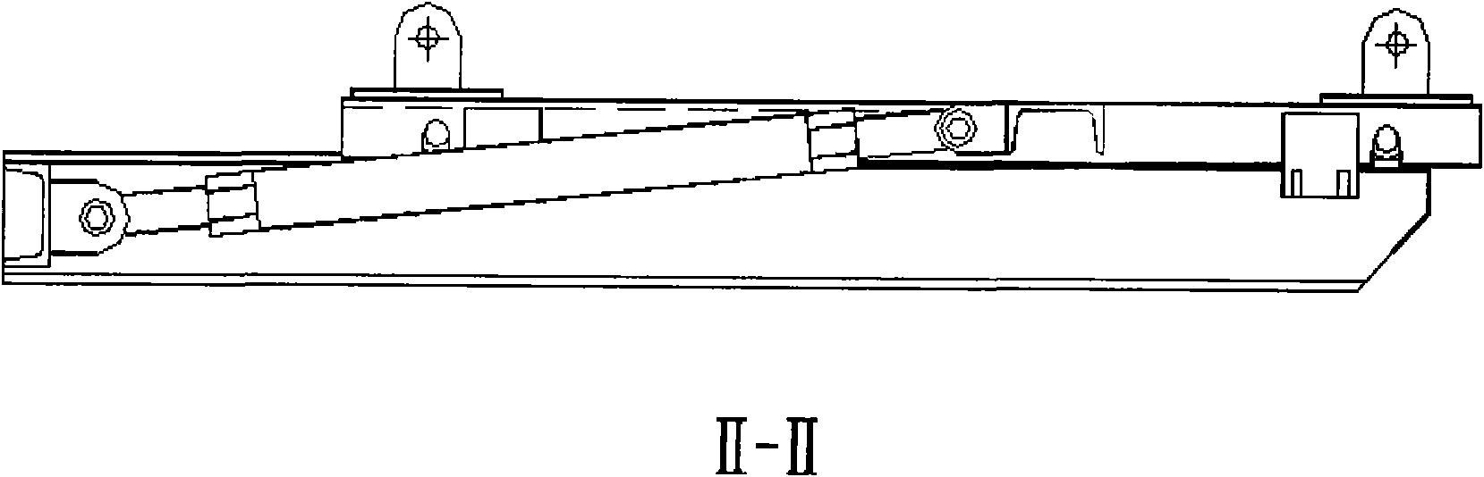
[0013] Refer to attached figure 1 and 2 , the present invention is by reverse " U " shape groove load-bearing beam (1), roller shaft (2), " I " font track beam (3), double " L " type groove plate (4), connecting horizontal bar ( 5), connecting channel steel (6) and adjusting bar (7) form. Through the steel sliding roller shaft (2), the upper inverted "U"-shaped groove load-bearing beam (1) and the lower "I"-shaped track beam (3) produce two-way sliding. The two ends of the load-bearing beam (1) are provided with double "L"-shaped grooved plates (4), which extend into the lower part of the upper flange of the "I"-shaped track beam (3) to limit the displacement in the vertical direction. Two load-bearing beams (1) that are parallel to each other and whose cross-sections are reversed "U" grooves are connected by a connecting horizontal bar (5) with double connecting ear plates in the middle; two parallel "I" shaped track beams (3 ) is connected at one end by a connecting chann...


PUM


Abstract

The invention discloses a bearing and sliding device for stretching and positioning in formwork engineering in the field of formwork construction. The device consists of bearing beams, track beams, a connecting transverse lever, connecting channel steel and an adjusting lever, and is characterized in that the bearing beams and the track beams form up-and-down composite beam structures capable of sliding longitudinally per se; two or more composite beams consisting of the bearing beams and the track beams are parallel; the connecting transverse lever is arranged between the parallel bearing beams to connect the bearing beams integrally; the connecting channel steel is arranged between the parallel track beams so as to integrally connect one end thereof; and the adjusting lever is arranged between the connecting transverse lever of the bearing beams and the connecting channel steel of the track beams so as to integrally hinge the connecting transverse lever with the connecting channel steel. The device solves the problem of detachable disassembly of the large-sized vertical formwork in the building construction and is suitable for sliding work of the load-bearing load.

Description

Technical field [0001] The invention belongs to the field of supporting construction machinery and equipment for construction application in formwork engineering. Background technique [0002] The construction field of formwork engineering in my country mainly involves civil construction, bridges, tunnels and water conservancy. Due to the continuous expansion of construction scale, the degree of mechanized construction of formwork engineering also needs to be rapidly improved. At present, in the construction of lock chambers, dams, tunnel holes, and bridge holes in water conservancy projects, the concrete pouring mainly depends on large formwork, and the movement of large formwork depends on formwork trolleys. The formwork trolley drives the large formwork to move along the direction of the track to realize mechanization. Operation. However, the existing formwork trolley can only move along the track direction during operation and cannot move laterally in the direction of ...

Claims


Application Information

Patent Timeline
Patent Type & Authority Applications(China)
IPC IPC(8): E04G19/00
Inventor 阎明伟
Owner BEIJING ACAD OF BUILDING ENG
Why Eureka
Try Eureka