System using solenoid groups to achieve electromagnetic guiding distance measurement while drilling

A guiding system and solenoid technology, applied in construction and other fields, can solve the problems of core technology confidentiality, limited measurement accuracy, monopoly, etc., and achieve the effect of easy distance measurement range, high measurement accuracy, and easy control

Active Publication Date: 2014-01-01
CHINA UNIV OF PETROLEUM (BEIJING)
View PDF2 Cites 0 Cited by
  • Summary
  • Abstract
  • Description
  • Claims
  • Application Information

AI Technical Summary

Problems solved by technology

At present, the measurement-while-drilling tools commonly used in China cannot directly measure the distance between adjacent wells, so it is difficult to meet the special requirements of detection-while-drilling for the distance between adjacent wells in wells with complex structures
Although foreign countries have developed electromagnetic guidance systems while drilling (such as MGT, RMRS, etc.) that can basically meet the above requirements, their core technologies are still kept secret and monopolized.
In addition, MGT (Magnetic Guidence Tool) uses a solenoid as a magnetic signal emission source, and the range of the MGT can be increased by increasing the current intensity of the solenoid coil, etc., but its measurement accuracy is limited, and it is generally used in double-horizontal wells; RMRS (Rotating Magnet Ranging System) is simple in structure and easy to use, and it is also the system with the highest measurement accuracy in the current guidance system while drilling. However, because the permanent magnet group sub-joint is used as the magnetic signal emission source, its signal source strength is severely limited. Difficulty increasing the ranging range of RMRS

Method used


Image

  • System using solenoid groups to achieve electromagnetic guiding distance measurement while drilling
  • System using solenoid groups to achieve electromagnetic guiding distance measurement while drilling
  • System using solenoid groups to achieve electromagnetic guiding distance measurement while drilling

Examples


Embodiment Construction

[0026] The present invention will be described below in conjunction with the drawings and embodiments.

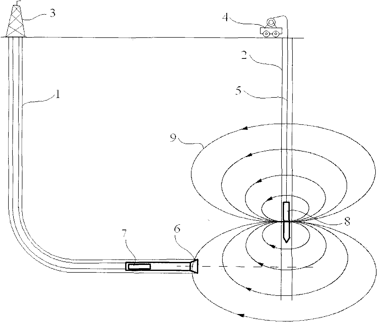
[0027] Such as figure 1 As shown, the hardware of the electromagnetic ranging and guidance system of the solenoid group while drilling is mainly composed of the solenoid group sub-section, the modified MWD, and ground equipment. The modified MWD is placed in the drilling well, following the traditional MWD installation position behind the drill bit, and detects the rotating magnetic field generated by the solenoid stack sub-joint in the adjacent well (drilled). Then, the detected magnetic vector signal is transmitted from the MWD to the ground computing system, and the relative position of the MWD to the sub-joint of the solenoid group is obtained. Furthermore, combined with the positional relationship between MWD and the drill bit, the relative position of the drill bit to the sub-section of the solenoid group can be calculated. Finally, the surface adjacent well spacing...


PUM


Abstract

The invention provides a system using solenoid groups to achieve the electromagnetic guiding distance measurement while drilling (MWD) and providing precise guiding measurement and calculation for the directional drilling control of dual horizontal wells, communicated wells, infill wells, relief wells and other complex wells. The system mainly comprises a nipple joint of the solenoid group, a converted MWD device, an adjacent well distance calculation system and surface equipment. By arranging two orthogonal solenoid groups as a magnetic signal emission source in a drilled well, the system of the invention can generate a rotating magnetic field just as that generated by the rotating magnetic nipple joint of an RMRS (rotating magnet ranging system), thus ensuring the measurement precision equivalent to that of the RMRS; meanwhile, by using the method for increasing the current intensity of the solenoid coil, the system of the invention can increase the intensity of the magnetic signal emission source and help extend the distance measurement range; and the invention has the advantages of high guiding accuracy, wide distance measurement range and simple structure, thus providing an effective hi-tech way for the detection and control while drilling the adjacent well distance.

Description

technical field [0001] The invention relates to a distance-while-drilling detection system for adjacent wells of complex-structured wells, and belongs to the technical field of underground resource drilling and production engineering. Background technique [0002] In the development of oil, natural gas, coalbed methane and other underground oil and gas resources, complex structure wells such as double horizontal wells, U-shaped wells, multi-lateral wells, cluster wells, infill wells and interconnected wells require accurate detection of the distance between adjacent wells while drilling . At present, the measurement-while-drilling tools commonly used in China cannot directly measure the distance between adjacent wells, so it is difficult to meet the special requirements of detection-while-drilling for the distance between adjacent wells in wells with complex structures. Although foreign countries have developed electromagnetic guidance systems while drilling (such as MGT, R...

Claims


Application Information

Patent Timeline
Patent Type & Authority Patents(China)
IPC IPC(8): E21B47/092E21B47/0228
Inventor 高德利刁斌斌
Owner CHINA UNIV OF PETROLEUM (BEIJING)
Why Eureka
Try Eureka