Eureka AIR delivers breakthrough ideas for toughest innovation challenges, trusted by R&D personnel around the world.

Remotely monitoring railroad equipment using network protocols

A technology of remote monitoring and network management protocol, which is applied in the field of remote monitoring of railway equipment using network protocols, and can solve problems such as difficulty in using monitoring systems

Inactive Publication Date: 2010-08-18
GENERAL ELECTRIC CO
View PDF0 Cites 8 Cited by
  • Summary
  • Abstract
  • Description
  • Claims
  • Application Information

AI Technical Summary

Problems solved by technology

This software configuration management initiative is difficult to implement with existing monitoring systems

Method used


Image

  • Remotely monitoring railroad equipment using network protocols
  • Remotely monitoring railroad equipment using network protocols
  • Remotely monitoring railroad equipment using network protocols

Examples


Embodiment Construction

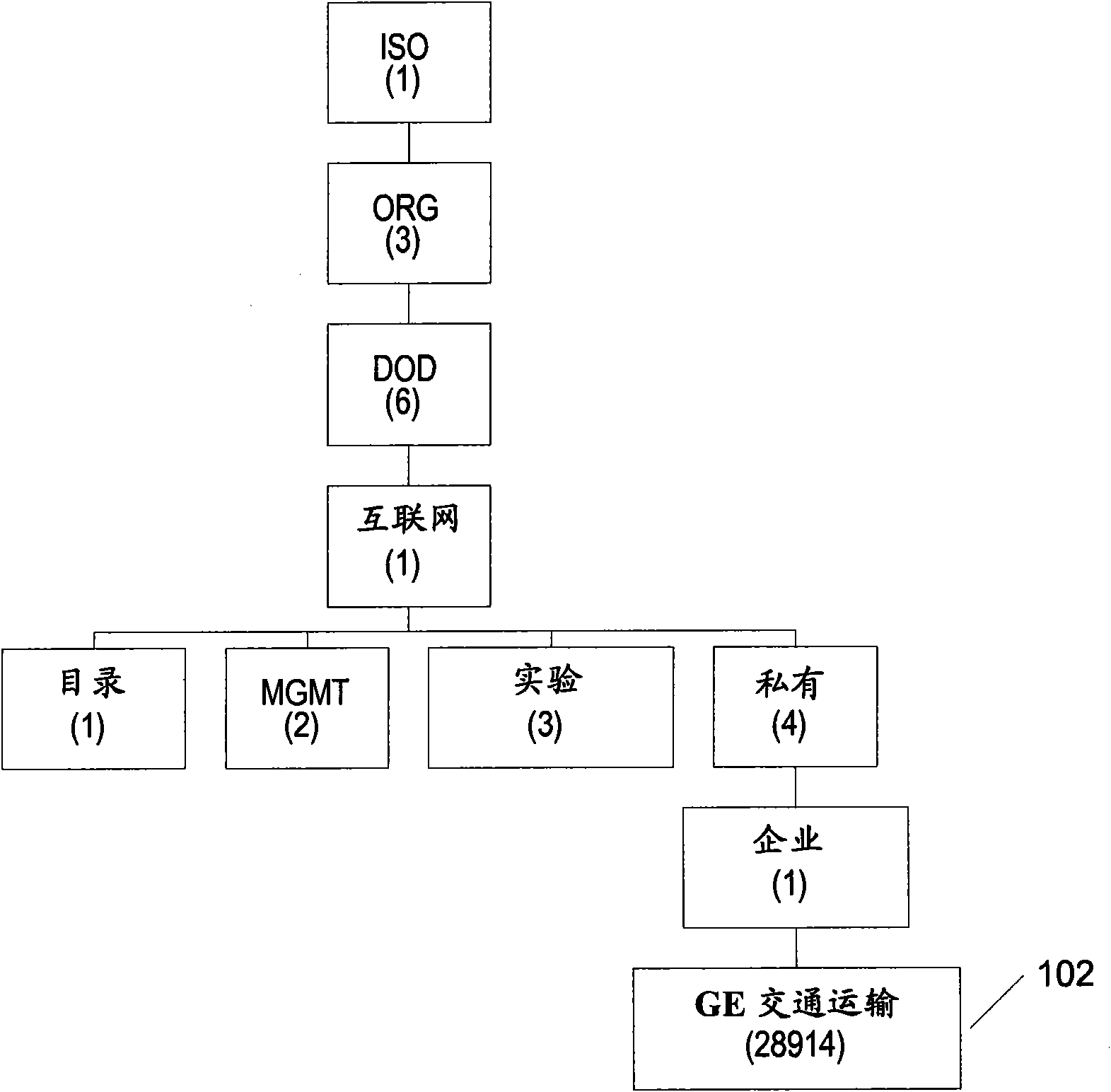
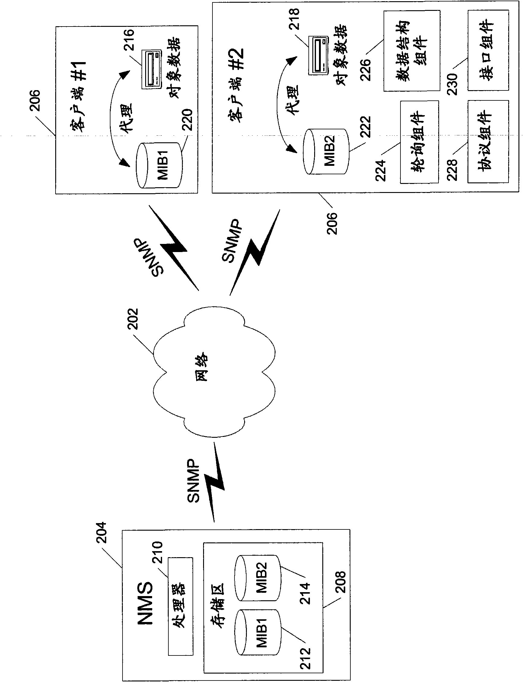
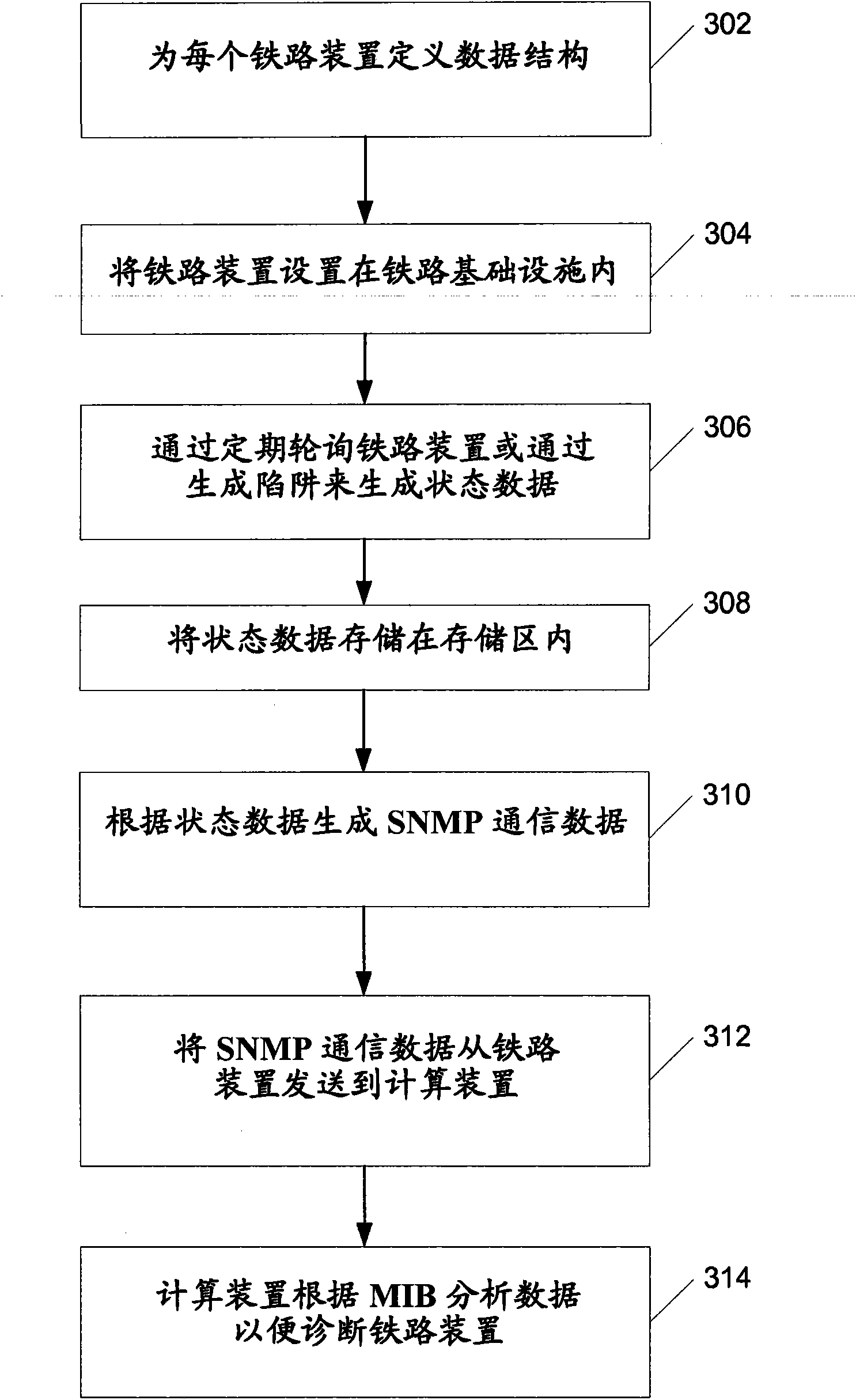
[0014] Embodiments of the present invention enable remote monitoring and diagnosis of railway equipment using network protocols. In one embodiment, the present invention uses an Internet Protocol (IP) network infrastructure that includes the Simple Network Management Protocol (SNMP) protocol with one or more associated Management Information Base or Block (MIB) data structures and network management tools , to enable remote monitoring and diagnosis of railway equipment. Each piece of railway equipment has a MIB associated with it, and includes support for IP and SNMP functionality either natively (eg, internally) or through add-ons or logic. The network management system utilizes the MIB to construct requests for information (eg, solicited data) from networked railway installations by utilizing SNMP. Alternatively or in addition, the railway equipment is configured to send SNMP traps (eg unsolicited data) to the network management system. Traps are used to remotely notify op...


PUM


Abstract

Remote monitoring and diagnosis of railroad devices using data structures defined for each of the railroad devices. The railroad devices are configured to populate the data structures with status data. The railroad devices transmit the status data for analysis using a network protocol. The analysis of the data results in reduced maintenance.

Description

Background technique [0001] When an event occurs within a rail system such as a level crossing warning system rail failure, rail breaks, signal lights going out, or communication links collapsing, these things may not be visible to the railroad on a macro level until there is a system-wide problem , for example when the entire signal network turns red, or when a public or local municipality issues a notice. Therefore, the railway office with macro visibility has only limited information for further maintenance. Therefore, there is a need for railroad offices to dispatch maintenance personnel to visually identify and troubleshoot anomalies at the incident site. [0002] Additionally, Federal Railroad Administration (FRA) regulations (CFR 236, Subpart H) require railroads to develop a software configuration management plan for all safety-critical processor-based controllers. This kind of software configuration management plan is difficult to implement with existing monitoring ...

Claims


Application Information

Patent Timeline
Patent Type & Authority Applications(China)
IPC IPC(8): B61L7/06
CPCB61L27/0088H04L43/10H04L67/12H04L43/00H04L41/0213H04L41/046H04L41/12H04L41/22H04L41/0681H04L43/0817H04L67/06H04L12/2602B61L27/53
Inventor J·M·弗里伊斯A·A·温加特纳D·J·赫林克西
Owner GENERAL ELECTRIC CO
Why Eureka
Eureka Blog
Learn More