Assembled mould structure with self-contained sliding core power

A combined mold and sliding core technology, applied in the field of injection molds, can solve problems such as unreliable cores, affecting product processing quality, and no support block mechanism, etc., to achieve the effect of flexible operation of the overall structure, novel design, and quick maintenance

Active Publication Date: 2012-07-25
NINGBO HUASHUO MOLDING & MACHINE
View PDF1 Cites 0 Cited by
  • Summary
  • Abstract
  • Description
  • Claims
  • Application Information

AI Technical Summary

Problems solved by technology

The middle part of the first slider is provided with a jack that penetrates up and down, and the two ends of the dovetail block are formed with a pushing part with an inclined surface, and one end of the side arm can be slidably inserted between the pushing part and the first slider; several types One end of the core is installed on the other end of the side arm and the dovetail block, and the other end extends into the cavity; the inclined guide pin has an inclined top end, which is inserted into the guide pin hole and its inclined top end is inserted into the first slide In the socket of the block; the movement of the inclined guide pin drives the first slider and the side wall to move in multiple directions; the core in this design is mainly driven by the movement of the inclined guide pin, and its power comes from the two modules Cage, but there is no support block mechanism at the rear end of the core after sliding, that is, it is easy to push it away during injection after the core slides, and the core is not secure in the product, which will affect the processing quality of the product

Method used


Image

  • Assembled mould structure with self-contained sliding core power
  • Assembled mould structure with self-contained sliding core power
  • Assembled mould structure with self-contained sliding core power

Examples


Embodiment Construction

[0020] The present invention will be further described in detail below in conjunction with the accompanying drawings and embodiments.

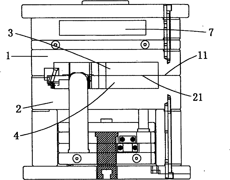
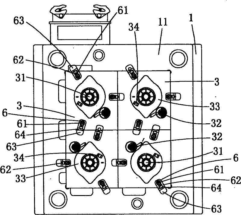
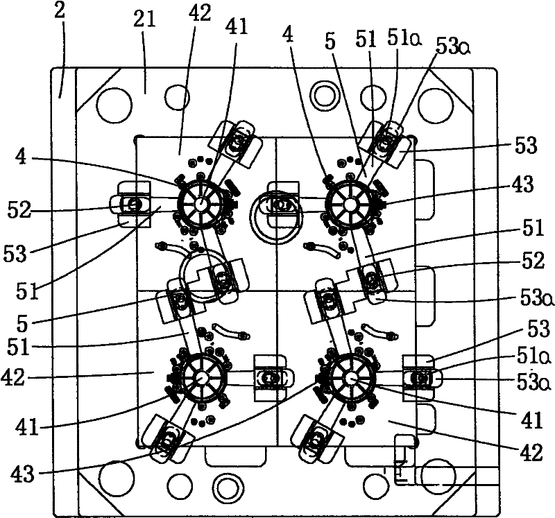
[0021] Such as Figure 1 to Figure 4 As shown, the icon numbers are explained as follows: fixed mold 1, contact surface 11, movable mold 2, working surface 21, fixed module unit 3, shaping cavity 31, gate 32, sinking platform 33, fixed insert hole 34, movable Module unit 4, movable cavity 41, movable mold unit body 42, movable insert hole 43, sliding core unit 5, slider 51, inclined end face 51a, hollow collar 52, positioning block 53, groove 53a, drive unit 6. Drive shaft 61, drive seat 62, bump body 63, positioning slope 64, hot runner system 7.

[0022] In the embodiment of the present invention, the combined mold structure with its own sliding core power includes a fixed mold 1 and a movable mold 2 that cooperate with each other. The working surface 21 of the movable mold 2 is inlaid with a movable module unit 4, and each movable module u...


PUM


Abstract

The invention discloses an assembled mould structure with self-contained sliding core power, which comprises a fixed mould and a movable mould matched with each other, wherein the working face of the movable mould is encrusted with movable mould units, the middle part of each movable mould unit is provided with a movable cavity, and the periphery of each movable mould unit is provided with three sets of sliding core units at an interval of equal radian along the center of the movable cavity; each sliding core unit is equipped with a slide block, and the external end side of the slide block isprovided with an obliquely arranged hollow lantern ring; the contact face of the fixed mould is embedded with fixed mould units, the middle part of each fixed mould unit is provided with a fixed cavity, and the periphery of each fixed mould unit is provided with three sets of driving units at an interval of equal radian along the center of the fixed cavity; and each driving unit is internally equipped with a protruded and obliquely arranged driving shaft. The assembled mould structure of the invention has the advantages that: by using the structure of splicing inclined shafts and sleeves, theoperation of the slide blocks can be realized without other external power; the same module is equipped with four sets of module units; the processing efficiency is high; and all units are in bolted connection, so the maintenance is quick and convenient.

Description

technical field [0001] The invention relates to the technical field of injection molds, in particular to a composite mold structure with sliding core power. Background technique [0002] For injection moulds, the slider-type core-pulling structure is a common method, such as the Chinese patent "Side Core-pulling Mechanism of Mold" (notification number CN201070822Y) whose patent number is ZL200720052914.8; The mold core, core-pulling main body and inclined guide pin; the mother template is provided with a mold cavity, accommodating groove and guide pin hole; the mold core is provided with a cavity; the core-pulling main body has a first slider, a dovetail block, a side arm and several cores. The middle part of the first slider is provided with a jack that penetrates up and down, and the two ends of the dovetail block are formed with a pushing part with an inclined surface, and one end of the side arm can be slidably inserted between the pushing part and the first slider; sev...

Claims


Application Information

Patent Timeline
Patent Type & Authority Patents(China)
IPC IPC(8): B29C45/26B29C45/33B29C45/36
Inventor 王洪彪
Owner NINGBO HUASHUO MOLDING & MACHINE
Why Eureka
Try Eureka