
Movable deck supporting device

A technology for supporting equipment and movable decks, applied in the direction of detachable decks, etc., can solve the problems of low work efficiency, reduced work efficiency, time-consuming and labor-intensive loading and unloading, and achieve the effect of shortening working hours and improving work efficiency

Inactive Publication Date: 2010-08-25
DAEDONG ENG +1
View PDF0 Cites 9 Cited by
  • Summary
  • Abstract
  • Description
  • Claims
  • Application Information

AI Technical Summary

Problems solved by technology

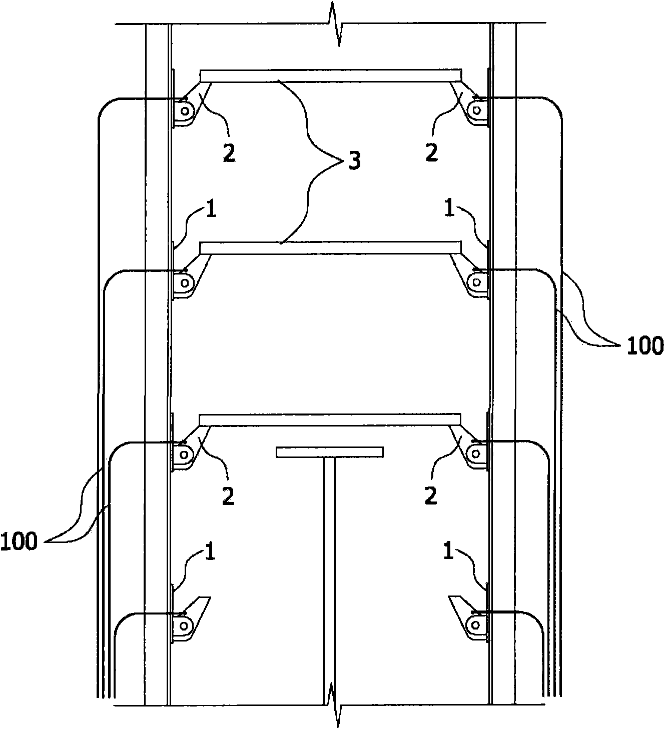
[0014] In the above-mentioned conventional movable deck support equipment, after loading the deck 3 on each layer, the steel cable 100 for controlling the rotation of the brake 2 must be repeatedly loosened / bound for each unloading operation, so the work efficiency is very low
[0015] Specifically, the staff first needs to move the vehicle equipped with the lifting device to the bottom of the layer to be loaded, then get down from the driver's seat, and repeatedly perform the work of binding / releasing the steel cables 100 of the corresponding layer, so the work efficiency is greatly reduced. , which consumes a lot of time and labor when carrying out loading and unloading work

Method used


Image

  • Movable deck supporting device
  • Movable deck supporting device
  • Movable deck supporting device

Examples


Embodiment Construction

[0027] The present invention will be described in detail below in conjunction with the accompanying drawings.

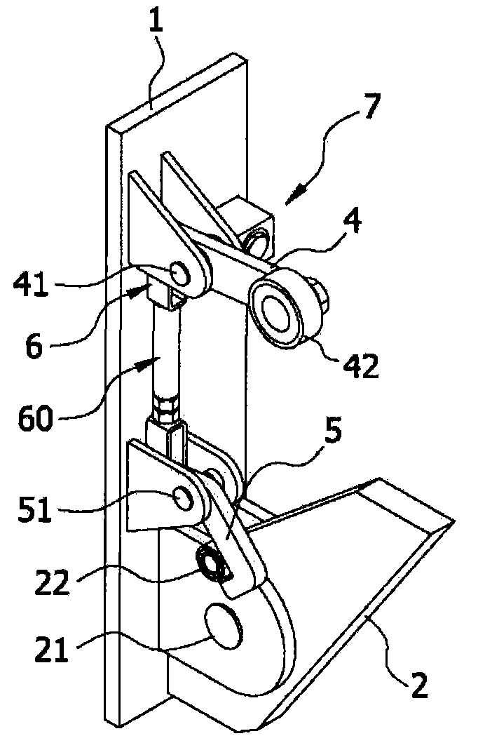
[0028] Fig. 3 is a perspective view of the disassembled state of the brake involved in the present invention; Fig. 4 is a perspective view of the combined state of the brake involved in the present invention; Fig. 5 is a side sectional view illustrating the relationship between the brake and the control device involved in the present invention ; Fig. 6 is a sectional view illustrating the working principle of the positioning device involved in the present invention; Fig. 7 is a side view illustrating the process of loading a deck on the support device involved in the present invention; Side view of the process of unloading the deck on the equipment.

[0029] As shown in Figures 3 to 6, the movable deck supporting device of the present invention includes a brake 2 that can rotate around the rotating shaft 21 and support the deck 3. The brake 2 is provided with a brake...


PUM


Abstract

The invention relates to a movable deck supporting device comprising a brake (2) which can rotate around a rotating shaft (21) to support a deck (3), wherein a control device which is linked with the ascending / descending deck and controls the brake to rotate is arranged on the brake; the control device comprises a link system (4) and a hook connecting rod (5); one end of the link system is arranged on a bracket (1) through a pivot (41) and the other end is arranged on the ascending / descending passage of the deck and connected with the deck and rotates; one end of the hook connecting rod is arranged on the bracket through a shaft (51) and the other end is in contact with a braking roller (22) formed on the brake so as to control the brake to rotate; the link system and the hook connecting rod are connected by a connecting rod (6), thereby realizing the linkage of the link system and the hook connecting rod. The movable deck supporting device has the advantages of enhancing the work efficiency and greatly shortening time needed in loading and unloading operation.

Description

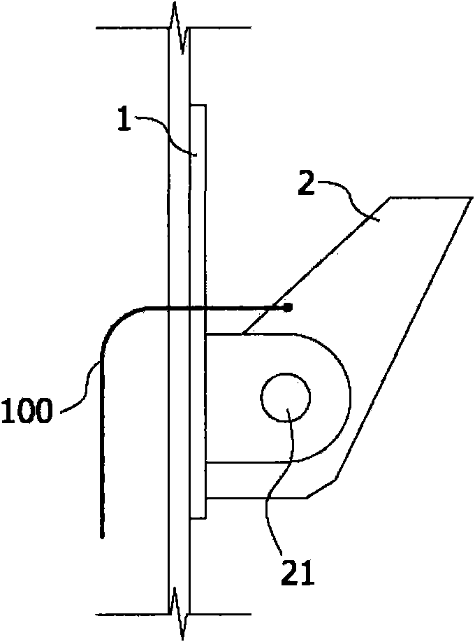
technical field [0001] The invention relates to movable deck support equipment, which improves the prior movable deck support equipment, improves work efficiency, and greatly shortens the time for loading and unloading work. Background technique [0002] Generally speaking, for ships carrying vehicles (PCC: Pure Car Carrier, PC&TC: Pure Car & Truck Carrier), in order to load more vehicles in a limited space, the vehicles are often loaded in layers. That is, support devices for supporting a deck for mounting a vehicle are formed in multiple layers inside the four pillars, and the deck for mounting a vehicle is mounted on each support device. [0003] Fig. 1 and Fig. 2 are respectively the front view and the oblique view of the brake of the movable deck supporting equipment in the past. [0004] As shown in FIG. 1 and FIG. 2 , in conventional movable deck supporting equipment, a brake 2 rotating around a rotating shaft 21 is provided on the inner surface of each pillar 1 inst...

Claims


Application Information

Patent Timeline
IPC IPC(8): B63B25/20
Inventor 李钟晚金相植
Owner DAEDONG ENG
Learn More