

Test tube bar code gluing machine
A sticking machine and test tube technology, which is applied in the field of labeling equipment, can solve the problems of inconvenience, uneven sticking of barcode labels, uncomfortable sticking, etc., and achieve the effect of uniform position, improved sticking efficiency, and easy reading
Active Publication Date: 2010-08-25
SHANGHAI JINYU LUOBO ELECTRONICS TECH
View PDF6 Cites 18 Cited by
- Summary
- Abstract
- Description
- Claims
- Application Information
AI Technical Summary
Problems solved by technology
At present, the sticking of labels on test tubes is basically done manually by staff. Manual sticking of barcodes often makes the sticking of barcode labels uneven, or the height of barcode labels on the test tube wall is uneven, which is difficult for the next step of machine-readable barcode labels. The procedure brings great inconvenience, and the efficiency of manual label sticking is very low, so it is not suitable for mass sticking work
Method used
View moreImage
Smart ImageViewing Examples

Examples
Embodiment Construction
Login to View More PUM
 Abstract
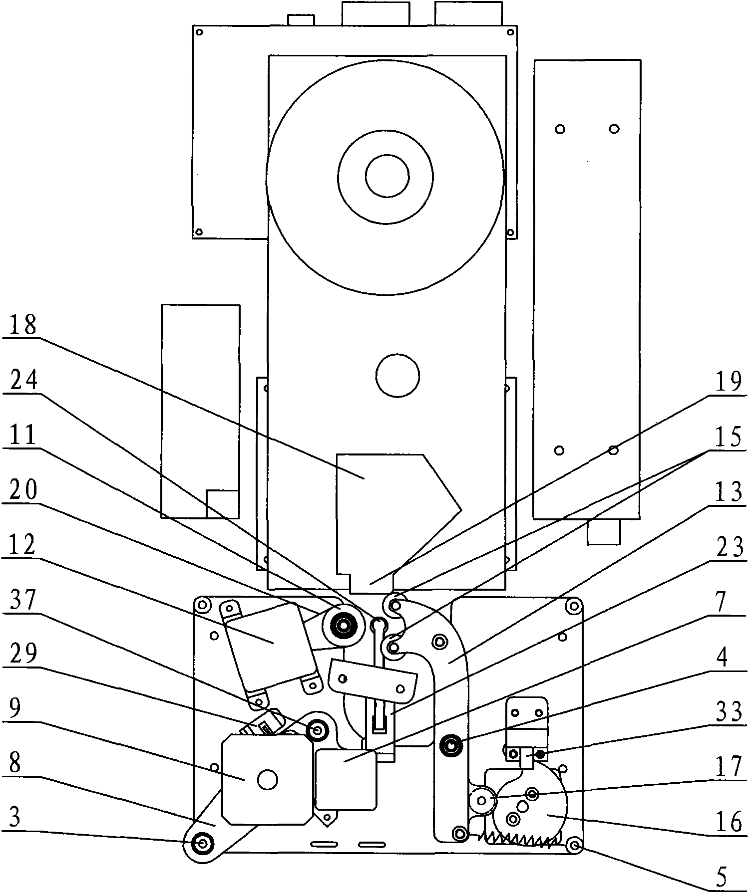
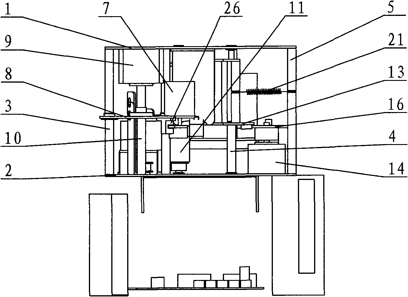
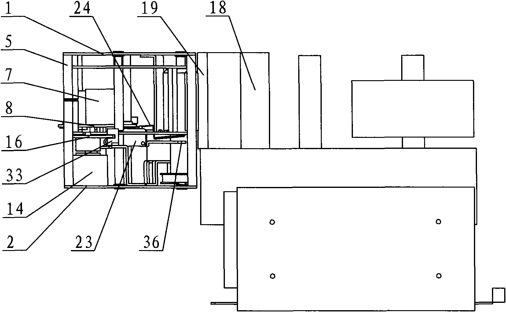
The invention provides a test tube bar code gluing machine, relates to a machine for gluing a label on a test tube, and aims to provide a test tube bar code gluing machine with simple structure, tidy gluing and high efficiency. The test tube bar code gluing machine comprises a frame and an execution part, wherein the execution part is arranged on the frame, and comprises a test tube clamping device, a test tube supporting device, a test tube rotating device and a bar code printing and gluing device; the test tube clamping device, the test tube supporting device, the test tube rotating device and the bar code printing and gluing device comprise a corresponding power part respectively; the power part drives the execution part to execute the following actions: a, the test tube supporting device executes or cancels axial support to the test tube, and adjusts the height of the test tube; b, the test tube clamping device executes or cancels clamping to the test tube; c, the test tube rotating device drives the test tube to circumferentially rotate; and d, the bar code printing and gluing device glues the bar code on the wall of the test tube.
Description
Test tube barcode paste machine technical field The present invention relates to a labeling device, in particular to a machine for labeling test tubes. Background technique In the laboratory and biochemical laboratory of the hospital, it is necessary to distinguish the collected test or experimental samples or record the test information. Now it is usually to paste the barcode label on the test tube where the sample is placed, and then record the barcode information in the computer management system. The sample information is then obtained by reading the barcode on the test tube. At present, the sticking of labels on test tubes is basically done manually by staff. Manual sticking of barcodes often makes the sticking of barcode labels uneven, or the height of barcode labels on the test tube wall is uneven, which is difficult for the next step of machine-readable barcode labels. The program brings great inconvenience, and the efficiency of manual labeling is very low, which...
Claims
Login to View More Application Information
Patent Timeline
 Patent Type & Authority Applications(China)
IPC IPC(8): B65C3/02B65C9/04B65C9/06B65C11/02G01N1/04G05B19/04
Inventor 金宇东陈鹏
Owner SHANGHAI JINYU LUOBO ELECTRONICS TECH