
Glass door clamping rail

A glass door and track technology, applied in door/window accessories, wing leaf arrangement, wing leaf components, etc., can solve the problem of reducing the overall quality of glass door assembly, unable to effectively control the position and height of glass 90 groups, and unable to stably Problems such as clamping glass 90

Inactive Publication Date: 2010-08-25
DOOR & WINDOW HARDWARE
View PDF3 Cites 40 Cited by
  • Summary
  • Abstract
  • Description
  • Claims
  • Application Information

AI Technical Summary

Problems solved by technology

[0006] 1) Because the inclination angles of the inclined surfaces 804, 826 on the clamping road 802 and the clamping strip 82 are not the same, and the two inclined surfaces 804, 826 are in line contact, when the two clamping strips 82 pass through the bolts 86 When the connecting piece 84 is close, the two clamping bars 82 tend to be skewed and cause an unstable clamping state in which the two clamping bars 82 and the glass 90 are in line contact, so the strength of the two clamping bars 82 to clamp the glass 90 is uneven and insufficient, so that the glass 90 cannot be firmly clamped, and the glass 90 cannot be assembled flat and skewed, which reduces the overall quality of the glass door assembly
[0007] 2) When the existing clamping strips 82 are close to the clamping glass 90, they will also move downward along the inclined surface 804 of the clamping road 802 at the same time, and will move different distances due to the difference in the thickness of the glass 90. It is easy to cause the situation that the location and height of the glass 90 cannot be effectively controlled

Method used


Image

  • Glass door clamping rail
  • Glass door clamping rail
  • Glass door clamping rail

Examples


Embodiment Construction

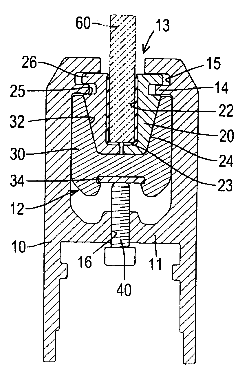
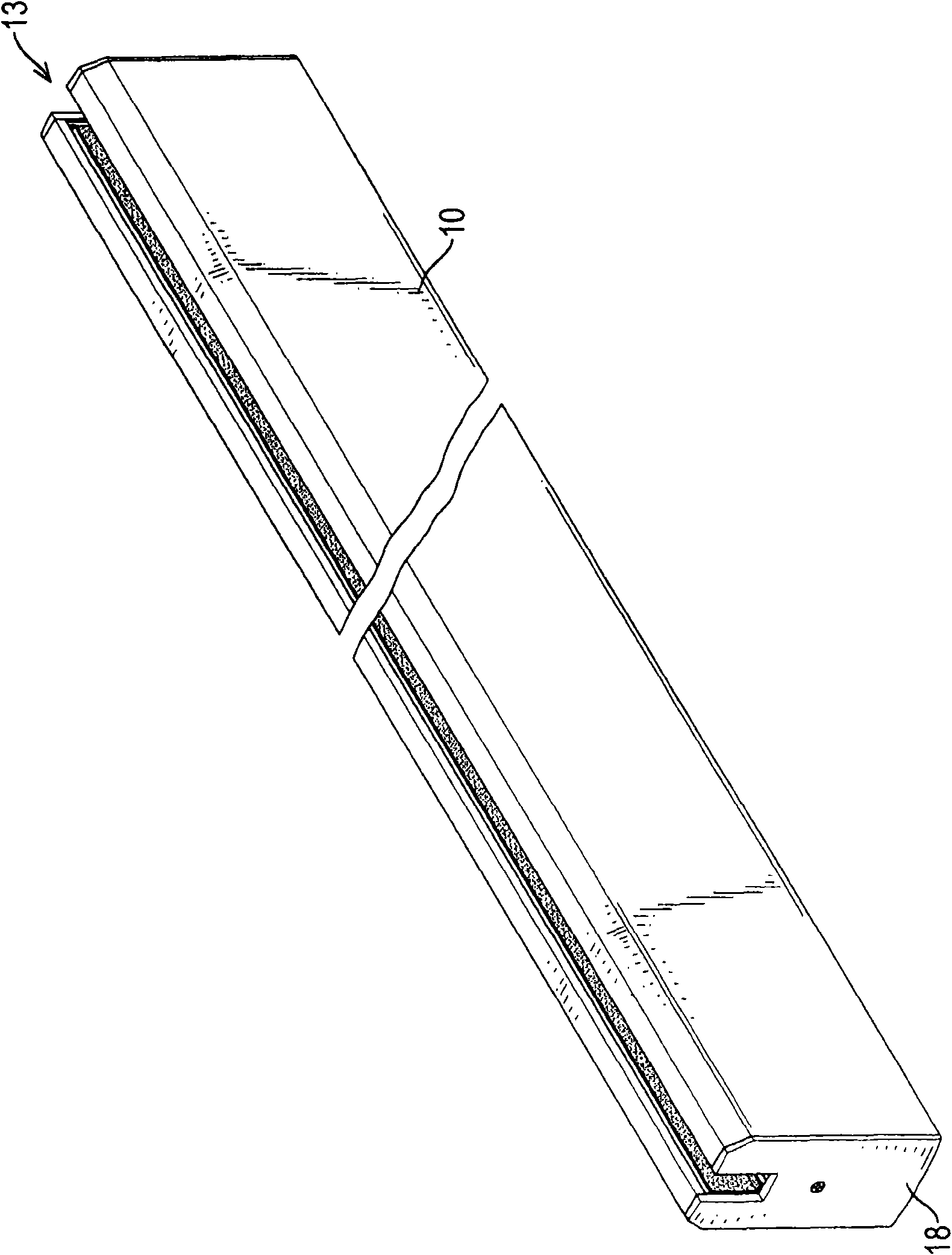
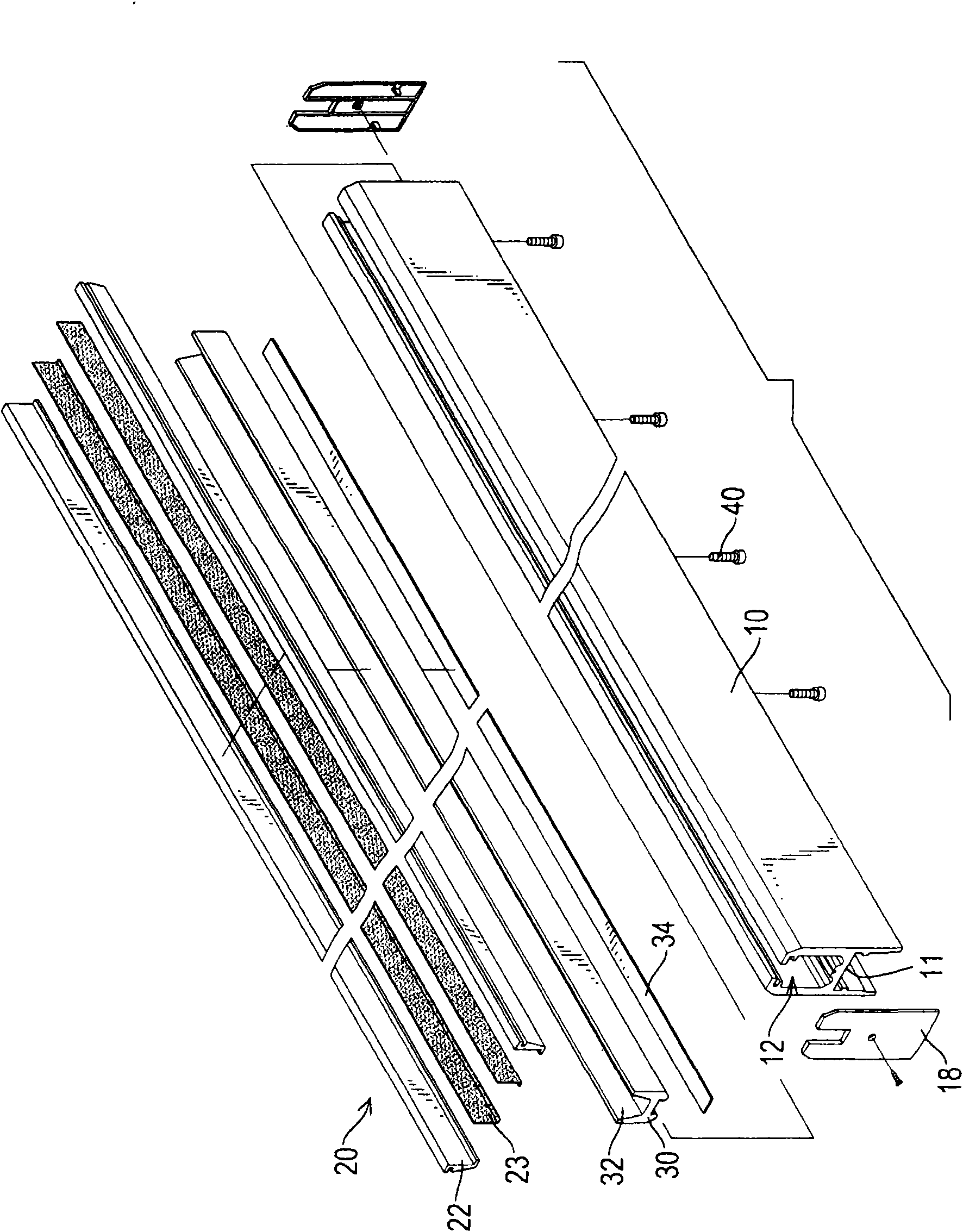
[0044] The present invention mainly provides a glass door clamping track, please refer to Figure 1 to Figure 3, as can be seen from the figures, the clamping track of the present invention mainly includes a long track body 10, the track body 10 is generally H-shaped section, and a spacer rib 11 is formed in the middle of the track body 10, and a clamping road 12 is formed on the side of the track body 10 located at the spacer rib 11, and a clamping channel 12 is formed on one end surface of the track body 10. The opening 13 connected to the track 12, and the two inner edge surfaces near the opening 13 of the track body 10 are protruded and formed with relative guide ribs 14, and are respectively formed between the two guide ribs 14 and the end edge of the opening 13 of the track body 10. There is a guide groove 15, and cover 18 can be provided at both ends of the track body 10 respectively.

[0045] In addition, two elongated clamping bars 20 are arranged in the clamping chann...


PUM


Abstract

The invention relates to a glass door clamping rail which is characterized in that a clamping channel is formed in a long rail body, two clamping strips which can mutually approach or separate are arranged in the clamping channel, clamping grooves which can be used for clamping glass are convexly arranged on the opposite lateral surfaces of the two clamping strips, an inclined face is formed at one ends of the two clamping strips differing from the other opposite lateral sides of the two clamping strips and facing towards the bottom surface of the clamping channel, a pushing strip which can be arranged in the rail body in an up-down movement way is additionally arranged in the clamping channel, one ends of the two clamping strips which form the inclined face are accommodated in the pushing strip, an inclined face which is matched with the inclined face of the two clamping strips is formed on the inner edge surfaces of two sides of the pushing strip, and at least one bolt which is usedfor pushing the pushing strip to move relative to the clamping channel of the rail body is arranged on the rail body.

Description

technical field [0001] The invention relates to a clamping track for a glass door, in particular to a clamping track which can be coordinated and adjusted to clamp glass of different thicknesses. Background technique [0002] Generally, when the existing glass door is assembled and installed, the clamping track is generally arranged on the top edge and the bottom edge of the glass door, so that the clamping track is pivotally combined with the door frame or the ground, and the existing clamping track is used for matching Glasses of different thicknesses can be clamped, and an adjustable clamping device will be provided, as shown in Figure 5, which is a clamping track of an existing clamping device, wherein the clamping track mainly includes a long The track body 80 has a clamping channel 802 formed in the track body 80, and an inclined surface 804 is formed on the inner edge surface of the clamping channel 802, and its clamping device mainly includes two clamping bars 82, a ...

Claims


Application Information

Patent Timeline
Patent Type & Authority Applications(China)
IPC IPC(8): E05D13/00E06B3/46
Inventor 林松辉
Owner DOOR & WINDOW HARDWARE
Learn More