
cooling method

A cooling method and coolant technology, applied in liquid cooling, engine cooling, coolant flow control, etc., can solve problems such as structure and coolant overheating, and achieve the effect of increasing protection and avoiding overheating damage

Inactive Publication Date: 2015-08-12
FORD GLOBAL TECH LLC
View PDF7 Cites 0 Cited by
  • Summary
  • Abstract
  • Description
  • Claims
  • Application Information

AI Technical Summary

Problems solved by technology

The coolant temperature in the first circuit is therefore lower than the opening temperature of the wax thermostat, so that the second circuit is not opened, although there is a situation where the heat introduced is still high and thus can lead to overheating of the structure and the coolant

Method used


Image

  • cooling method

Examples


Embodiment Construction

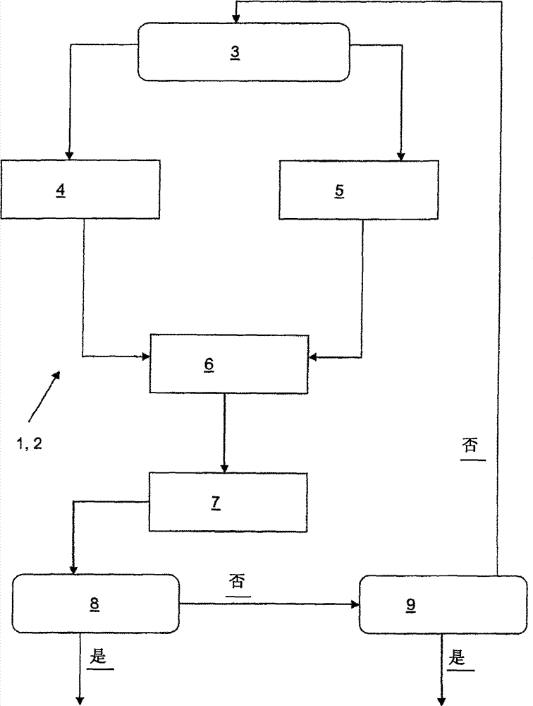
[0029] Cooling method 2 is preferably implemented in internal combustion engines with a so-called split cooling design. In a split cooling design, the internal combustion engine has a coolant jacket on the cylinder block side and a coolant jacket on the cylinder head side. Preferably, the regulating valve is arranged in the water outlet housing, ie a separate part connected to the cylinder head, and in a preferred embodiment as a thermostat, the regulating valve controls the total flow of coolant, eg for cooling and heating. The regulating valve can also be arranged in the coolant jacket on the cylinder head side. Of course, the control valve can also be arranged at other suitable locations, as long as the coolant flow through the coolant jacket on the cylinder block side can be prevented during the warm-up phase or after a cold start of the internal combustion engine. Another thermostat affecting coolant flow through the cylinder block may be provided in the cylinder block i...


PUM


Abstract

The cooling strategy (2) involves dividing a medium cycle into a cylinder head side and a block sided coolant jacket. A coolant control valve is provided, which prevents the flow of coolant to the block sided coolant jacket and releases until a predetermined temperature is reached. A warm-up model of the combustion engine is implemented in a control unit for receiving the temperature during a start of the combustion engine and operating data of the internal combustion engine and for determining a heat input from the received temperature and the received operating data (6).

Description

technical field [0001] The invention relates to a method for cooling an internal combustion engine having at least one medium-containing circuit divided into a cylinder block-side coolant jacket and at least one cylinder head-side coolant jacket, wherein a coolant regulating valve is provided to prevent, first of all, The coolant flows to the coolant jacket of the cylinder block and does not release the fluid until a preset temperature is reached. Background technique [0002] In order to increase the warm-up performance of internal combustion engines, the principle of split cooling is increasingly being used, ie the division of the coolant circuit into a cylinder block-side coolant circuit and at least one cylinder head-side coolant circuit. The cooling circuit of the at least one cylinder head can also be referred to as a first subcircuit, wherein the cooling circuit of the cylinder block can also be referred to as a second subcircuit. The circuit on the cylinder head sid...

Claims


Application Information

Patent Timeline
Patent Type & Authority Patents(China)
IPC IPC(8): F01P7/14
CPCF01P3/02F01P7/167F01P2003/028
Inventor I·伦兹M·吕茨J·梅林R·弗里切
Owner FORD GLOBAL TECH LLC
Learn More