Supercharge Your Innovation With Domain-Expert AI Agents!

Three-range potential difference meter

A potentiometer and range technology, applied in the field of instruments for measuring DC voltage, can solve the problems of increasing the volume of the instrument, complicated and troublesome structures of switches and instruments, etc.

Inactive Publication Date: 2010-08-25
骆晓英
View PDF1 Cites 0 Cited by
  • Summary
  • Abstract
  • Description
  • Claims
  • Application Information

AI Technical Summary

Problems solved by technology

[0003] Since the second and third stepping discs have auxiliary discs, the number of layers of the second and third stepping disc switches is increased, thereby increasing the volume of the instrument and complicating the structure of the switch and the instrument. If the measurement data of the second and third stepping discs are found to be out of tolerance during the verification process, it is very troublesome to correct the inner layer resistance of the second and third stepping disc switches

Method used


Image

  • Three-range potential difference meter
  • Three-range potential difference meter

Examples


Embodiment Construction

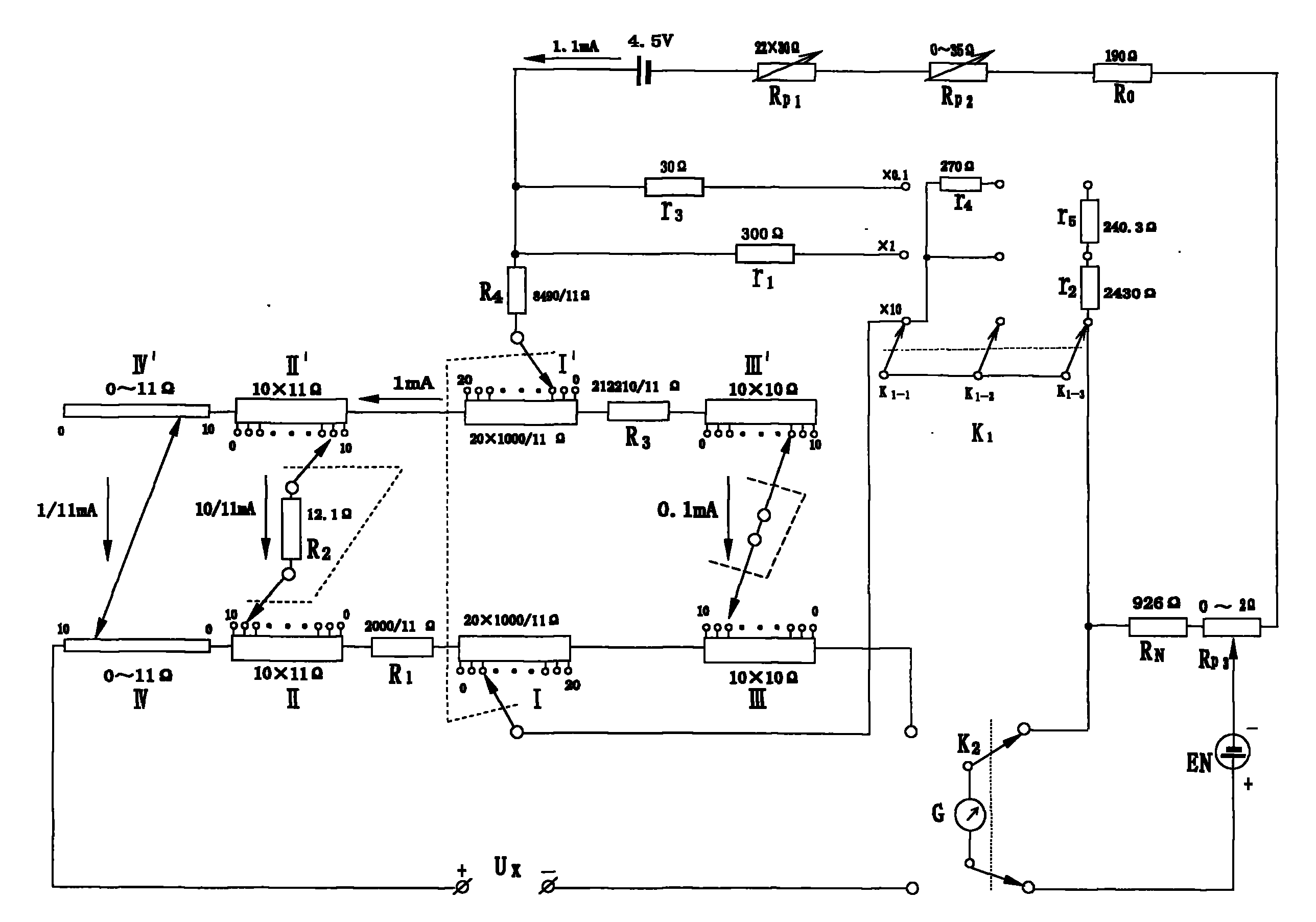
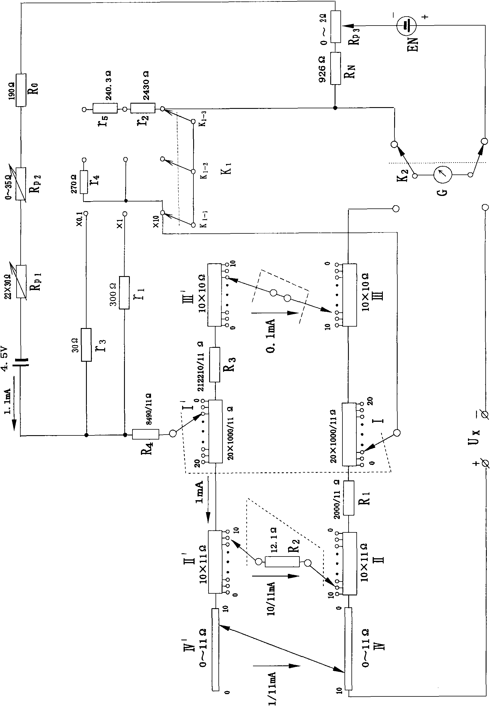
[0009] In Figure 1, in the ×10 range, when the three stepping disks and one double-sliding wire disk are all set to "0", the resistance value on the left side between the two brushes of the first stepping disk is equal to 2121Ω, and the resistance value on the right side is equal to 21210Ω, therefore, 10 / 11 of the total current between the two brushes of the first step disc flows on the left side, and 1 / 11 flows on the right side. When three stepping disks and one double-sliding wire disk are placed on other contacts, the resistance increased by each measuring disk is equal to the resistance reduced by the replacement disk, so the resistance on the left and right sides between the two brushes of the first stepping disk The value does not change.

[0010] The standard operating current of the potentiometer is 1.1mA, ×10 range, the current between the two brushes of the first step plate is 1mA on the left, and the current on the right is 0.1mA, and the current on the left flows ...


PUM


Abstract

The invention relates to a three-range potential difference meter for measuring direct current voltage. In the three-range potential difference meter, three stepping panels and one double slide wire panel, and three measuring panels and one measuring panel slide wire are respectively and directly connected with each other by wires and do not use switches; and thus, when being used for measurement, the potential difference meter can not be affected by variations or thermoelectric potential, and each measuring panel or substitute panel is composed of resistors with the same resistance value without using a bracket panel, so that the volume of the complete instrument is reduced. The three ranges can be switched through two shunt resistors, and the minimum resolution is 0.1 mu V.

Description

technical field [0001] The invention relates to an instrument for measuring DC voltage. Background technique [0002] Application number 200510062271.0 has announced a three-range potentiometer with three stepping discs and a double-sliding line disc. Its second and third stepping discs are respectively composed of measuring discs, substituting discs and auxiliary discs. The resistance value on the replacement disk is the same, every time a resistance is added to the measuring disk, the replacement disk will reduce the same resistance, because the second step disk is not set at the 0th contact, when the third step disk is set to a different value The total resistance of the circuit changes. When the second stepping disc is set at the 0th contact, the total resistance of the circuit remains unchanged when the third stepping disc is set at different values. Outside the disk, an auxiliary disk is added to distinguish the circuit connection of the second stepping disk with the ...

Claims


Application Information

Patent Timeline
Patent Type & Authority Applications(China)
IPC IPC(8): G01R17/20
Inventor 骆晓英
Owner 骆晓英
Features
  • R&D
  • Intellectual Property
  • Life Sciences
  • Materials
  • Tech Scout
  • Unparalleled Data Quality
  • Higher Quality Content
  • 60% Fewer Hallucinations
Learn More