Sensor and imaging system for the remote detection of an object

A technology for detecting targets and imaging systems, applied in the field of remote measurement, which can solve the problems of increasing system complexity and price

Inactive Publication Date: 2010-08-25
桥梁公路中心实验室
View PDF1 Cites 9 Cited by
  • Summary
  • Abstract
  • Description
  • Claims
  • Application Information

AI Technical Summary

Problems solved by technology

These constraints increase the complexity and price of such systems, and additionally, limit the use of static observation

Method used


Image

  • Sensor and imaging system for the remote detection of an object
  • Sensor and imaging system for the remote detection of an object
  • Sensor and imaging system for the remote detection of an object

Examples


Embodiment Construction

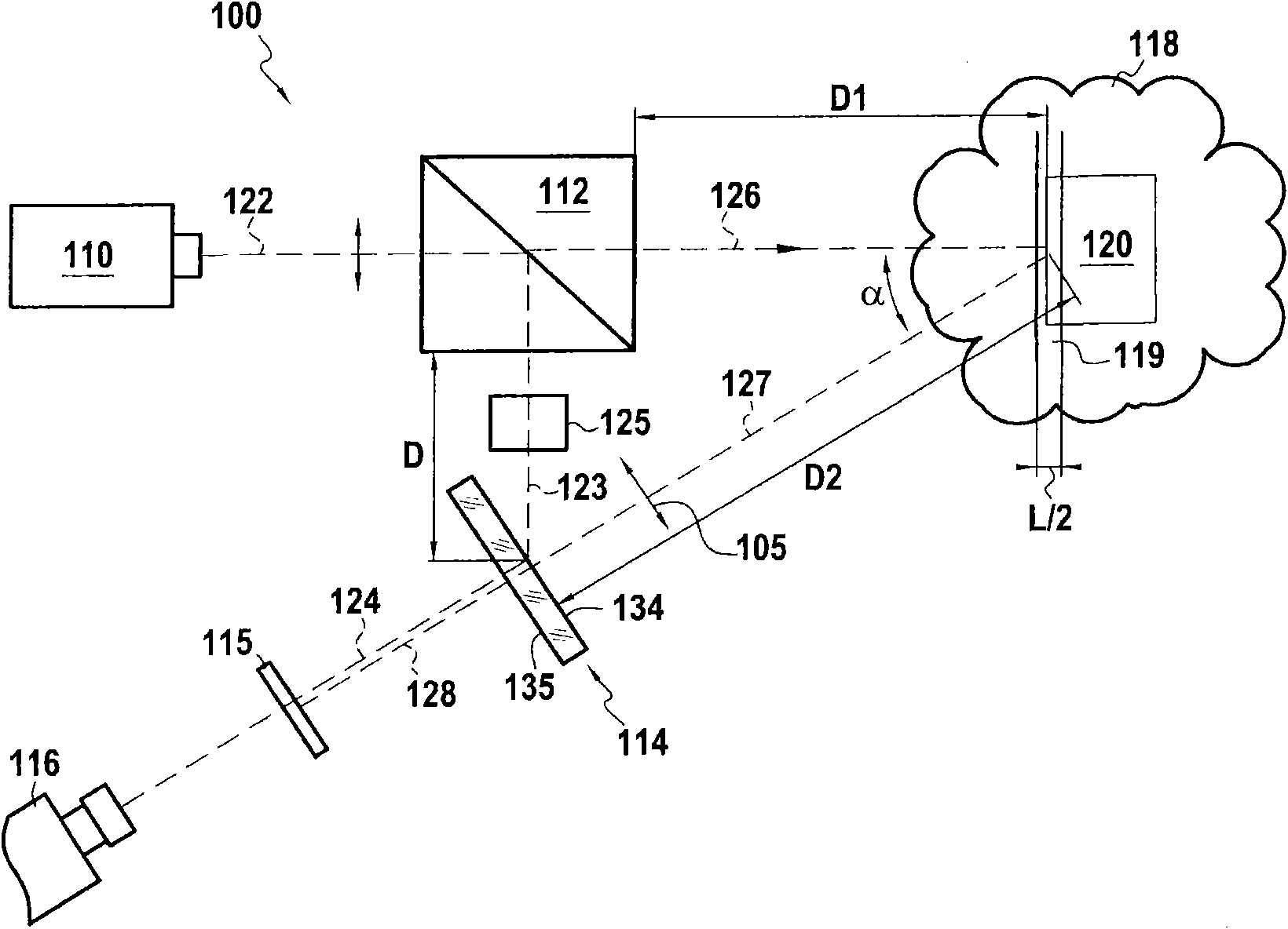
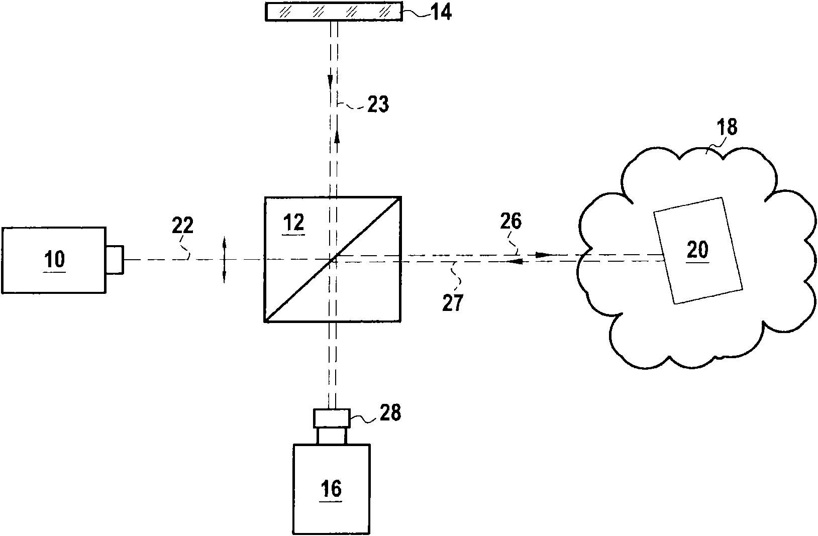
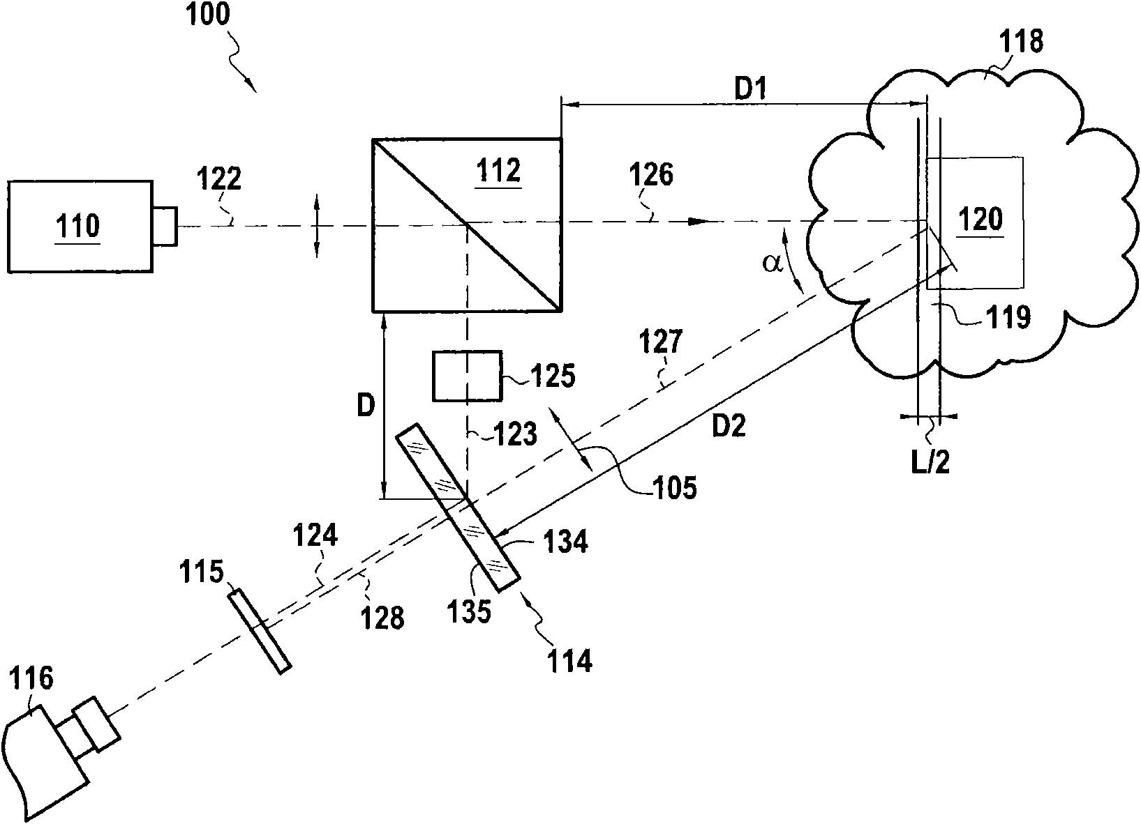
[0067] Figure 2 shows a sensor 100 of the present invention.

[0068] The sensor 100 includes a light source 110 , a beam splitting cube 112 , a photorefractive crystal 114 , a polarizer 115 and a detector 116 .

[0069] The light source 110 is a laser source emitting a source beam 122 towards a target 120 for measurement. In the context of the present invention, the light source may likewise be a laser, laser diode, LED or the like.

[0070] The target 120 is located in a diffuse medium 118, which may be a particulate atmosphere such as the atmosphere in fog or rain, or may be living tissue or other tissue (not to mention if the medium 118 is not diffuse, the measurement The same is possible). The beam splitting cube 112 is equipped in the path of the source beam 122 and splits it into two beams:

[0071] a reference beam 123, the reference beam 123 is deflected by 90 degrees relative to the direction of the source beam 122;

[0072] The incident light beam 126 , which is...


PUM


Abstract

The invention discloses a sensor for remotely detecting an object, the sensor comprising: a light source having a coherence length that is short relative to the distance between the sensor and the object; a splitter splitting the emitted light beam into an incident beam and a reference beam; a photorefractive crystal recording a hologram on interfering reception of the reference beam and of the reflected beam reflected by an object illuminated by the incident beam, and playing back the hologram in a diffracted beam that is re-emitted by the crystal by anisotropic diffraction under the effect of the reference beam; a detector recording information on receiving the diffracted beam; and a polarizing filter that eliminates the major fraction of the reflected beam as transmitted by the crystal on receiving the reflected beam; such that the detector receives only the diffracted beam from the crystal. Both the sensor and imaging systems incorporating the sensor enable measurements to be made through diffusing media.

Description

technical field [0001] The present invention relates to the remote measurement of the position and / or shape of an object, especially when the object is located in a diffuse medium. More specifically, consider three applications: [0002] Measure the movement and / or distance of multiple targets (whether coordinated or not) on a large scale, especially under adverse meteorological conditions; [0003] On a medium scale, for cars on the road, detecting and / or identifying obstacles or other cars through fog or rain; [0004] On a small scale, the structure of cells in biological tissues is measured. Background technique [0005] Different technical solutions are known for remotely measuring the position of a target. Some of them are especially suitable for measurements in diffuse media. [0006] Firstly, on a large scale, it is known to use theodolites for measuring the relative positions of objects. These sensors consist in firing an infrared laser beam to hit a reflective...

Claims


Application Information

Patent Timeline
Patent Type & Authority Applications(China)
IPC IPC(8): G01S17/00G01S17/89G01N21/45G01S17/95
CPCG03H2001/0467G03H1/0005G03H2001/2276G03H2001/2244G03H2001/0038G03H2222/31G03H2001/0083G03H2210/63G01N21/453G03H2260/36G03H2001/0268G03H1/04G03H2001/026G01N21/4795G03H2223/26
Inventor 弗雷德里克·塔亚德艾蒂安·贝兰
Owner 桥梁公路中心实验室
Why Eureka
Try Eureka