
Low windage resistance mitre gate

A technology of miter gates and air resistance, applied in the direction of lift valves, valve details, engine components, etc., can solve the problems of complex and difficult production processes, and the incompatibility of miter gate parts, and achieve simple production processes and low manufacturing costs Effect

Inactive Publication Date: 2010-09-01
梁浩鉴
View PDF6 Cites 3 Cited by
  • Summary
  • Abstract
  • Description
  • Claims
  • Application Information

AI Technical Summary

Problems solved by technology

The size of the miter gate with this structure is ever-changing due to the square frame-shaped valve body according to the actual requirements. For each size, it is necessary to manufacture blades and blade gears of corresponding sizes to cooperate with it, and the position of the power unit is also required. Different designs are required. In this way, not only the production process is complicated and difficult, but also the cost is high. Most of the accessories of the miter gates of various sizes cannot be interchanged, which brings great inconvenience to maintenance; in addition, due to the existing Some accessories including sealing rubber strips need to be installed on the technical blades, resulting in uneven surface of the blades, which makes the wind resistance of the blades relatively large

Method used


Image

  • Low windage resistance mitre gate
  • Low windage resistance mitre gate
  • Low windage resistance mitre gate

Examples


Embodiment Construction

[0013] Now in conjunction with accompanying drawing and embodiment the present invention is described in further detail:

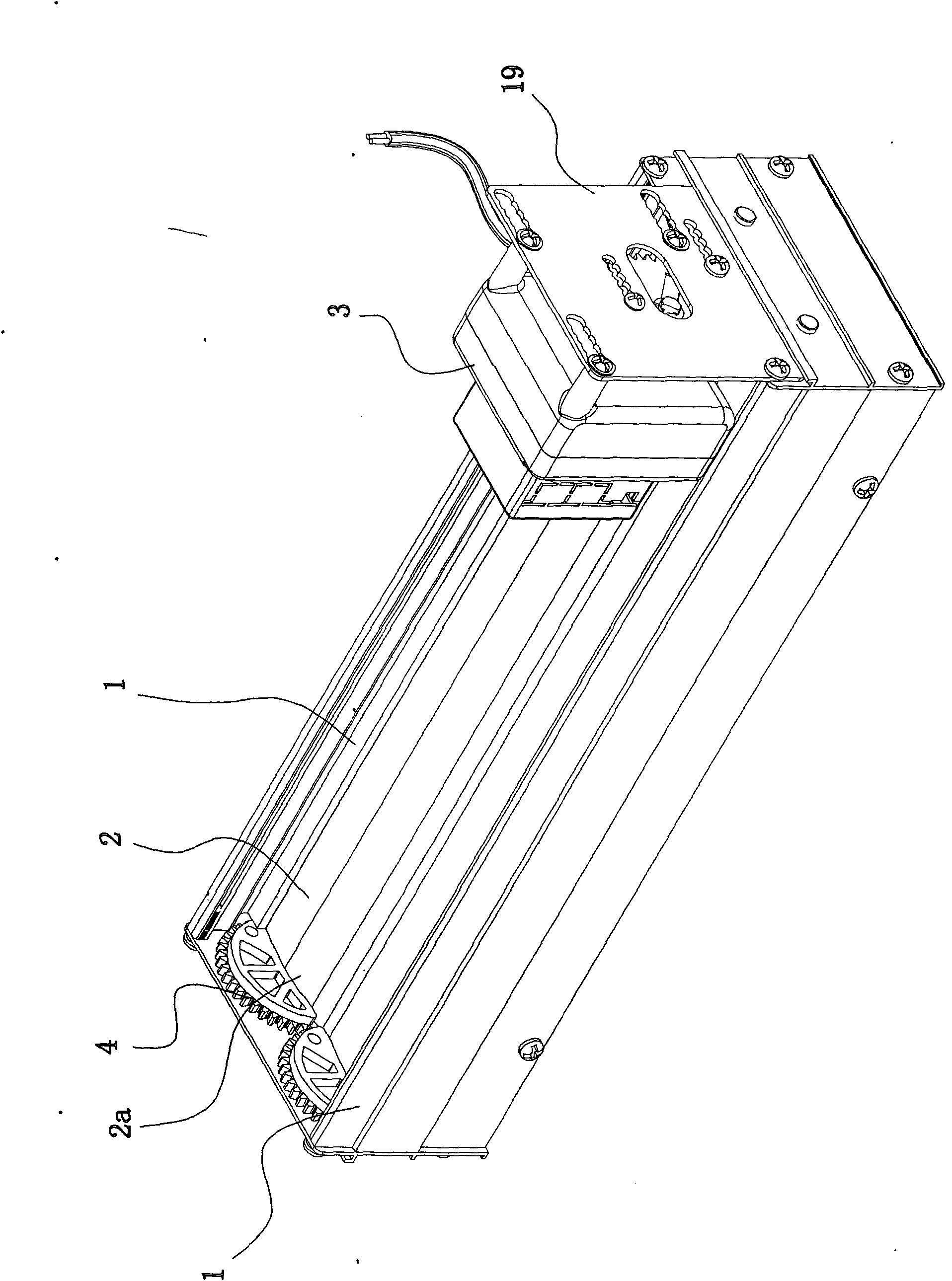
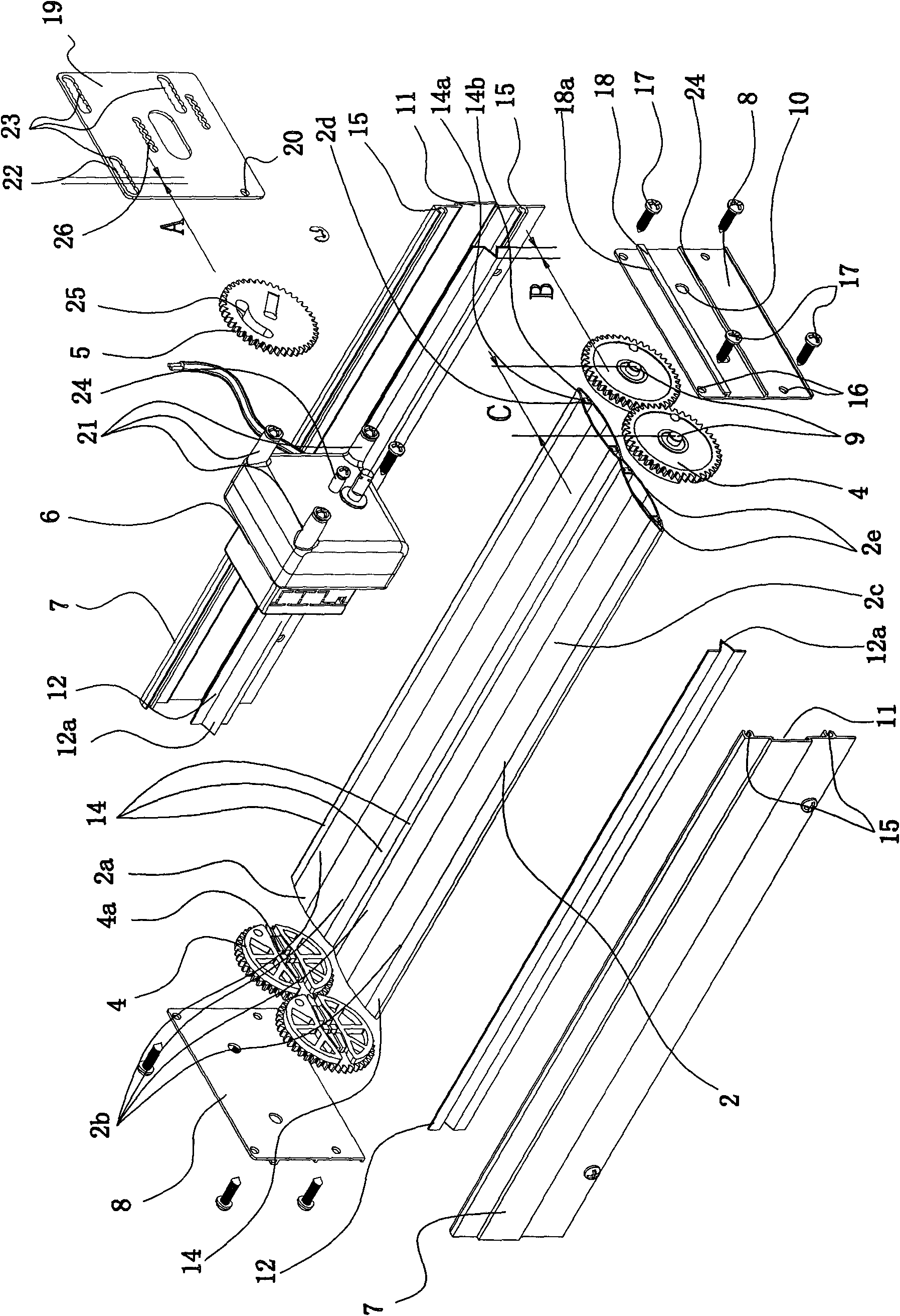
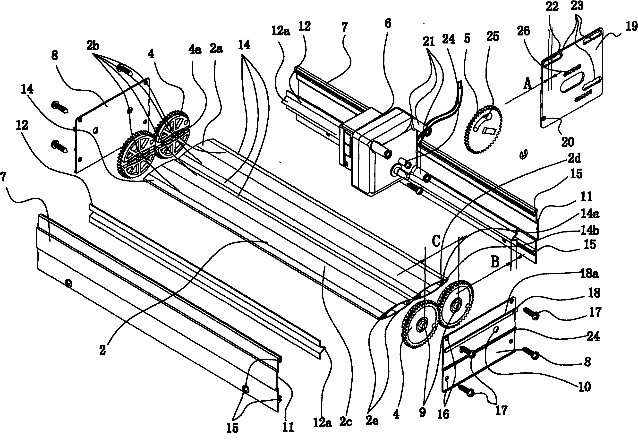
[0014] As shown in the figure, the present invention includes a square frame-shaped valve body 1, more than one blade 2 arranged in the square frame-shaped valve body 1, and a power transmission mechanism 3 for driving the rotation of the blades 2. The power transmission mechanism 3 includes 2 The vane gear 4 at the end 2a, the drive gear 5 that drives the vane gear 4 to rotate, the power device 6 that drives the drive gear 5 to rotate, the square frame-shaped valve body 1 includes two long side frames 7, fixed on the two long side frames 7 The two short side frames 8 at the end, the blade gear 4 is connected to the shaft hole 10 of the short side frame 8 of the square valve body 1 through the rotation of the shaft 9, and the long side frame 7 is cut from the long side frame aluminum alloy profile. The short side frame 8 is cut from the short side frame al...


PUM


Abstract

The invention relates to a low windage resistance mitre gate. The mitre gate comprises a square frame-shaped valve body, more than one vane arranged inside the square frame-shaped valve body, and a power transmission mechanism used for driving the vane to rotate, wherein the square frame-shaped valve body comprises two long side frames and two short side frames fixed at the two ends of the two long side frames. The low windage resistance mitre gate is characterized in that a slot is formed on an inner side of the long side frames; a sealing aluminum plate provided with a sealing boss is plugged in the slot; an upper surface and a lower surface of the vane are arched surfaces; sealing rubber strips are fixed on end faces of two sides of the vane; a translot of which the mouth faces upwardsis formed on an outer side face of the short side frames; a power device fixing and mounting plate is plugged in the translot; a power device is provided with more than three mounting and fixing feet; an insertion hole which consists of a plurality of through holes transversely and uniformly distributed is formed on the fixing and mounting plate which corresponds to the mounting and fixing feet; adjacent through holes are overlapped with one other; and the center distance of two adjacent through holes is shorter than the distance from the outer edge of the sealing boss to the root part of thesealing boss. Compared with the prior art, the low windage resistance mitre gate has the advantages of simple production process, low manufacturing cost, and interchanging of most parts of the mitre gates of different sizes.

Description

Technical field: [0001] The invention relates to a ventilation valve. Background technique: [0002] Existing valves for air-conditioning, the miter gate, are composed of a square-shaped valve body, more than two blades arranged in the square-shaped valve body, and a power transmission mechanism that drives the blades to rotate. The blade gear, the driving gear and the power device at the end of each blade, the power device drives the driving gear to rotate, the driving gear drives the blade gears that mesh with each other to rotate, and each blade gear drives each blade to open in a herringbone shape or the two sides of each blade are stacked head to tail Close the box-shaped valve body port together. The size of the miter gate with this structure is ever-changing due to the square frame-shaped valve body according to the actual requirements. For each size, it is necessary to manufacture blades and blade gears of corresponding sizes to cooperate with it, and the position o...

Claims


Application Information

Patent Timeline
IPC IPC(8): F16K1/16F16K27/02F16K1/32F16K31/53
Inventor 梁浩鉴
Owner 梁浩鉴
Learn More