Multi-hop wireless communication system and method

A technology of multi-hop wireless communication and transmission method, applied in the field of multi-hop wireless communication system and its transmission

Inactive Publication Date: 2010-09-01
FUJITSU LTD
View PDF0 Cites 5 Cited by
  • Summary
  • Abstract
  • Description
  • Claims
  • Application Information

AI Technical Summary

Problems solved by technology

However, there is still the problem of allowing two-way communication (i.e., in the uplink and download directions) without interference

Method used


Image

  • Multi-hop wireless communication system and method
  • Multi-hop wireless communication system and method
  • Multi-hop wireless communication system and method

Examples


Embodiment Construction

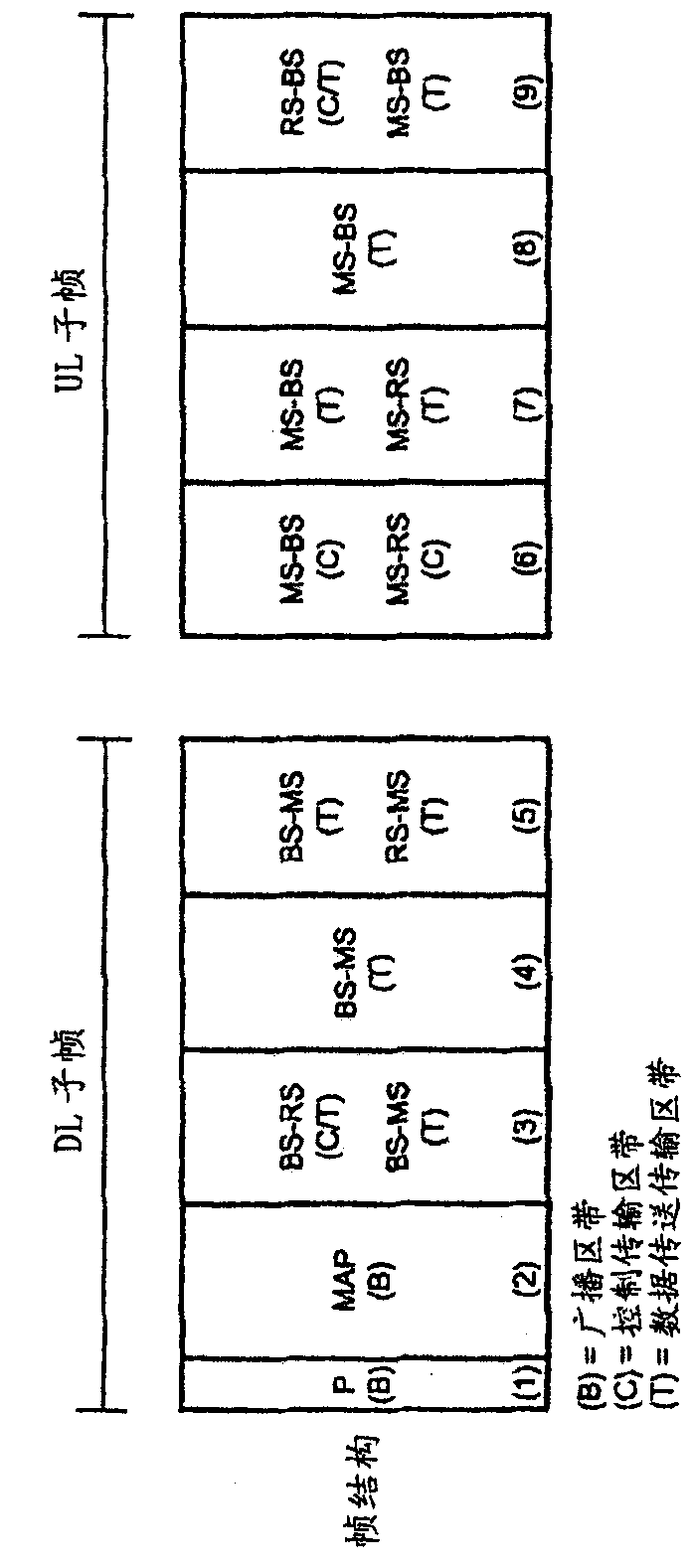
[0045] Embodiments of the present invention provide a frame structure for a multi-hop communication system, which is an extension of the standard TDD frame structure. The proposed frame structure has many benefits, as described later in this specification.

[0046] Frame structure and details of system operation

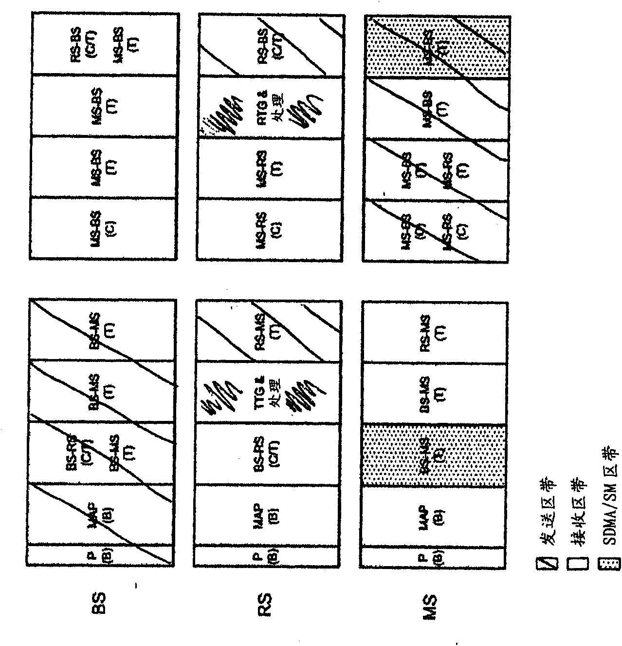
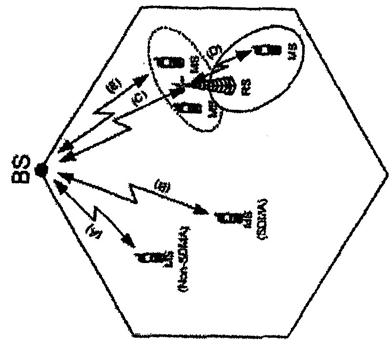
[0047] The proposed frame structure is designed for the situation that the control information sent from the head node controlling the overall medium access can be received by all the slave nodes working in the network. Furthermore, it is designed in such a way that legacy single-hop TDD mobile devices that are relay-agnostic can work within the new relay-enabled system.

[0048] If the control information cannot be received from the head node (or source device), an additional frame period is required for two-hop transmission. This is because the control information sent by the source device to the intermediate device cannot be received by the destination device wi...


PUM


Abstract

A transmission method for use in a two-hop wireless communication system, the system comprising a source apparatus, a destination apparatus and an intermediate apparatus. The method comprises following steps: employing a downlink transmission frames to transmit information; the downlink transmission frames comprise a first zone transmitting a radio signal from a base station to a relay station, asecond zone transmitting the video signal from the relay station to a mobile station and a third zone between the first zone and the second zone for directly transmitting the video signal from the base station to the mobile station.

Description

[0001] This application is a divisional application of the patent application No. 200710141986.4 filed on August 17, 2007 with the title of invention "communication system". technical field [0002] The present invention relates to wireless communication technology, more specifically, to a multi-hop wireless communication system and its transmission method. Background technique [0003] There is currently a lot of interest in the use of multi-hop techniques in packet-based radio communications and other communication systems, where this means that such techniques not only extend the coverage but also increase the capacity (throughput) of the system. [0004] In a multi-hop communication system, communication signals are sent from a source device to a destination device via one or more intermediate devices in a communication direction along a communication path (C). Figure 4 A single-cell two-hop network comprising a base station BS (referred to as a "Node B" NB in ​​the cont...

Claims


Application Information

Patent Timeline
Patent Type & Authority Applications(China)
IPC IPC(8): H04B7/26H04W16/26
CPCH04L5/0007H04L12/66H04L5/0037H04B7/15592H04B7/2606H04W84/047Y02B60/50H04L5/0023H04B7/2043Y02D30/70H04L27/2602H04L5/1469
Inventor 迈克尔·约翰·比默斯·哈特周跃峰
Owner FUJITSU LTD
Why Eureka
Try Eureka