System and device

A sample and channel technology, applied in the field of systems and devices, can solve the problems of increasing device costs and limiting the volume to a small size.

Active Publication Date: 2020-02-04
爱尔兰国立大学都柏林大学学院
View PDF12 Cites 0 Cited by
  • Summary
  • Abstract
  • Description
  • Claims
  • Application Information

AI Technical Summary

Problems solved by technology

Although the size of the container is not limited, the requirement to centrifuge the sample with the container held at a depth of 3 mm has been observed (in order to remove debris from the subject of interest and maintain image clarity under the microscope) and this will limit the volume in each cavity to very small values
Multiple lumens can be used but would require precise x and / or y movement which would increase the cost of the device

Method used


Image

  • System and device
  • System and device
  • System and device

Examples


Embodiment Construction

[0116] The present invention describes a system comprising an image capture device with a magnifying lens, a cartridge designed to hold a specific volume of liquid sample, image analysis software designed to identify and count specific items / particles of interest and suites to simplify procedures for end users.

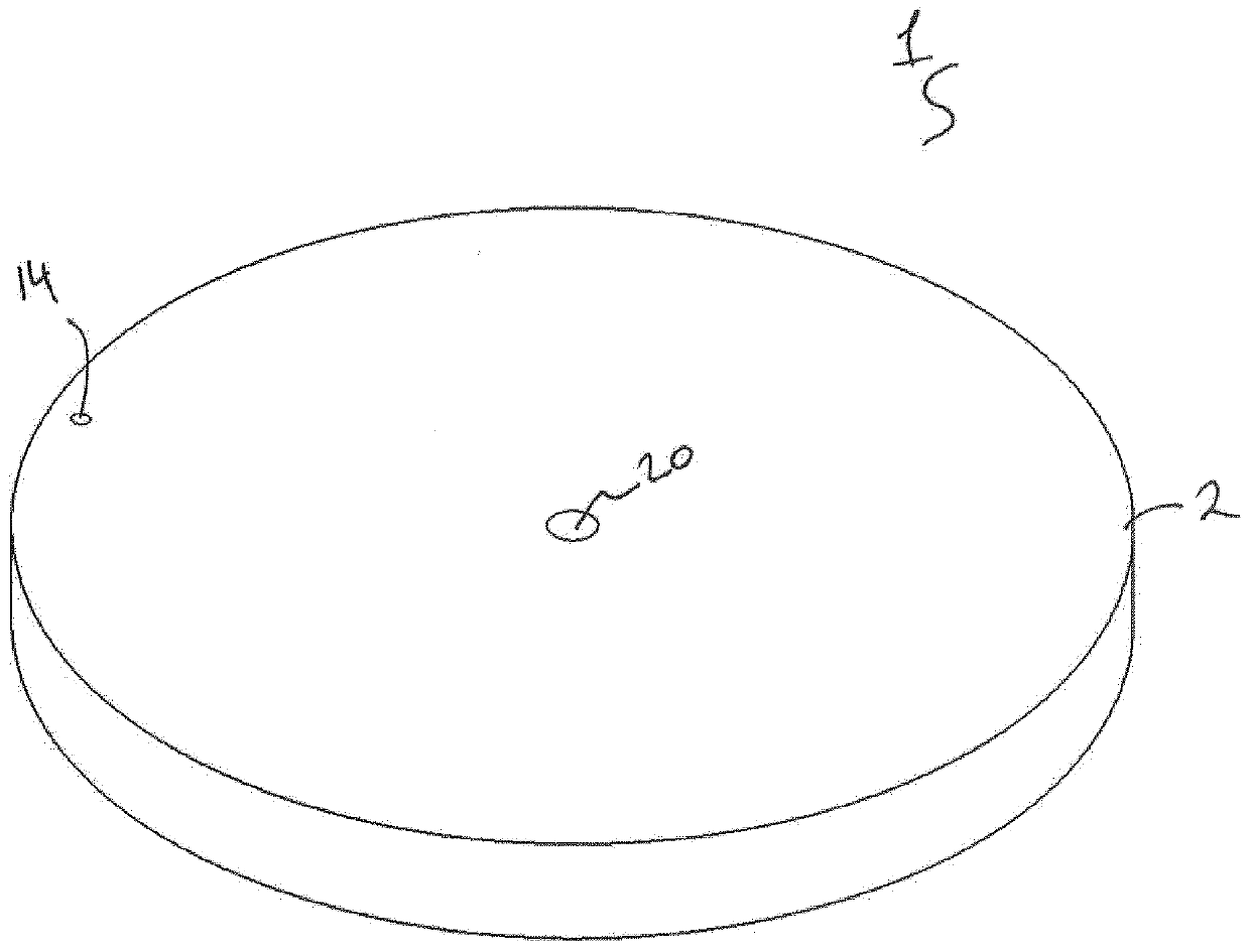
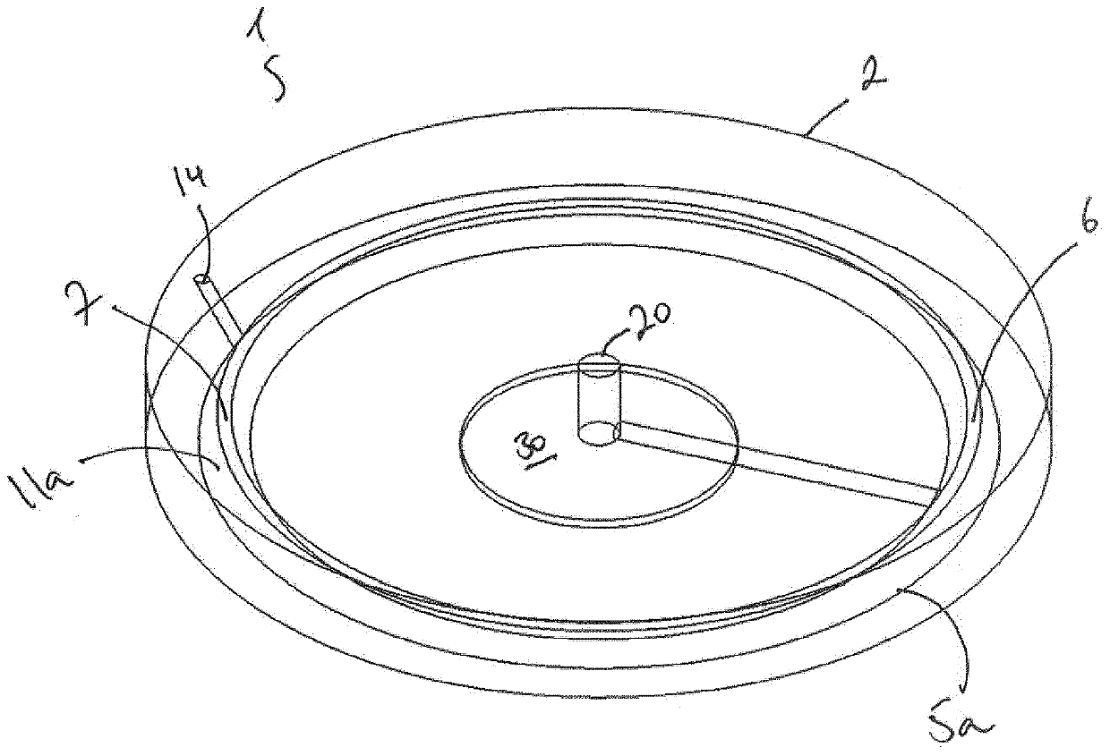
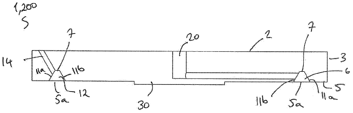
[0117] Referring now to the accompanying drawings, in which Figures 1, 2 and Figure 8 One embodiment of the cartridge of the present invention is shown. In particular, FIG. 1 illustrates a perspective view of one embodiment of the cartridge of the present invention and is generally designated by the reference numeral 1 . Figure 2A with Figure 8 A section of the cartridge 1 of FIG. 1 is shown. Cassette 1 comprises a housing 2 with an outer wall 3 , a bore 30 configured to accommodate an actuator or motor drive shaft and a support 5 . The housing 2 of the cartridge 1 may or may not have an outer wall 3 . The support 5 forms the base 5 a of the closed sample-rece...


PUM


Abstract

A cassette for use in concentrating matters in a sample suspension is provided. The cassette comprises a housing having a support and an enclosed sample-receiving channel, the enclosed sample-receiving channel having an upper portion and a base connected by at least two walls. The upper portion is configured to have a width less than a width of the base and a depth greater than 400 [mu]m.

Description

technical field [0001] The present invention relates to systems and devices for the qualitative and quantitative analysis of particulate matter in liquid samples by optical microscopy. In particular, the systems and devices relate to the measurement of biological elements, such as parasite eggs, in biological samples, such as fecal samples. Background technique [0002] The qualitative and quantitative analysis of particles in a given sample is of significant value for a wide range of diagnostic purposes, in animal and human health, and in environmental research. Qualitative refers to confirming the presence or absence of specific biological elements while quantitatively provides the amount of these elements. The standard method currently used in laboratories is the flotation technique, which uses microscopy to detect, identify and quantify specific biological material (eg, parasites in fecal matter, protozoa in water, microorganisms in soil, etc.) within a sample. The res...

Claims


Application Information

Patent Timeline
Patent Type & Authority Applications(China)
IPC IPC(8): G01N15/14B01L3/00C12M1/00C12M1/34C12Q1/04G01N21/03G01N15/00
CPCG01N15/1456G01N2015/0088G01N2015/1486G01N15/1463B01L3/502715B01L3/50273B01L3/502738B01L2200/0684B01L2300/0803B01L2300/0851B01L2300/0858B01L2300/161B01L2400/0487B01L3/502B01L2300/023B01L2300/168B01L2400/06G01N2015/1488
Inventor T·德瓦尔R·易卜拉希米M·克里沃鲁奇科V·罗巴斯金T·麦克欧文W·奥康纳D·斯科尔斯
Owner 爱尔兰国立大学都柏林大学学院
Why Eureka
Try Eureka