Fuel injection valve and fuel injection device

A fuel injection valve and fuel pressure technology, which is applied to fuel injection devices, fuel injection devices with sensors, and charging systems, etc., can solve the problems of increasing labor and time for connector connection operations, and complicated electrical wiring processing. Avoid labor and time, achieve the effect of root number

Active Publication Date: 2010-09-01
DENSO CORP +1
View PDF1 Cites 10 Cited by
  • Summary
  • Abstract
  • Description
  • Claims
  • Application Information

AI Technical Summary

Problems solved by technology

In this way, the electrical wiring that connects the external equipment such as the engine ECU and the two connectors extends from the two connectors of the fuel injection valve respectively. Therefore, in the state where the fuel injection valve is mounted on the engine, these The handling of electric wiring becomes complicated, and the labor and time of the connector connection operation are increased

Method used


Image

  • Fuel injection valve and fuel injection device
  • Fuel injection valve and fuel injection device
  • Fuel injection valve and fuel injection device

Examples


no. 1 approach

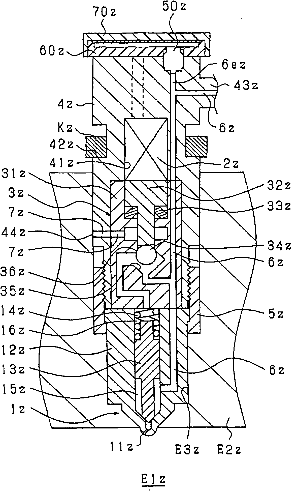
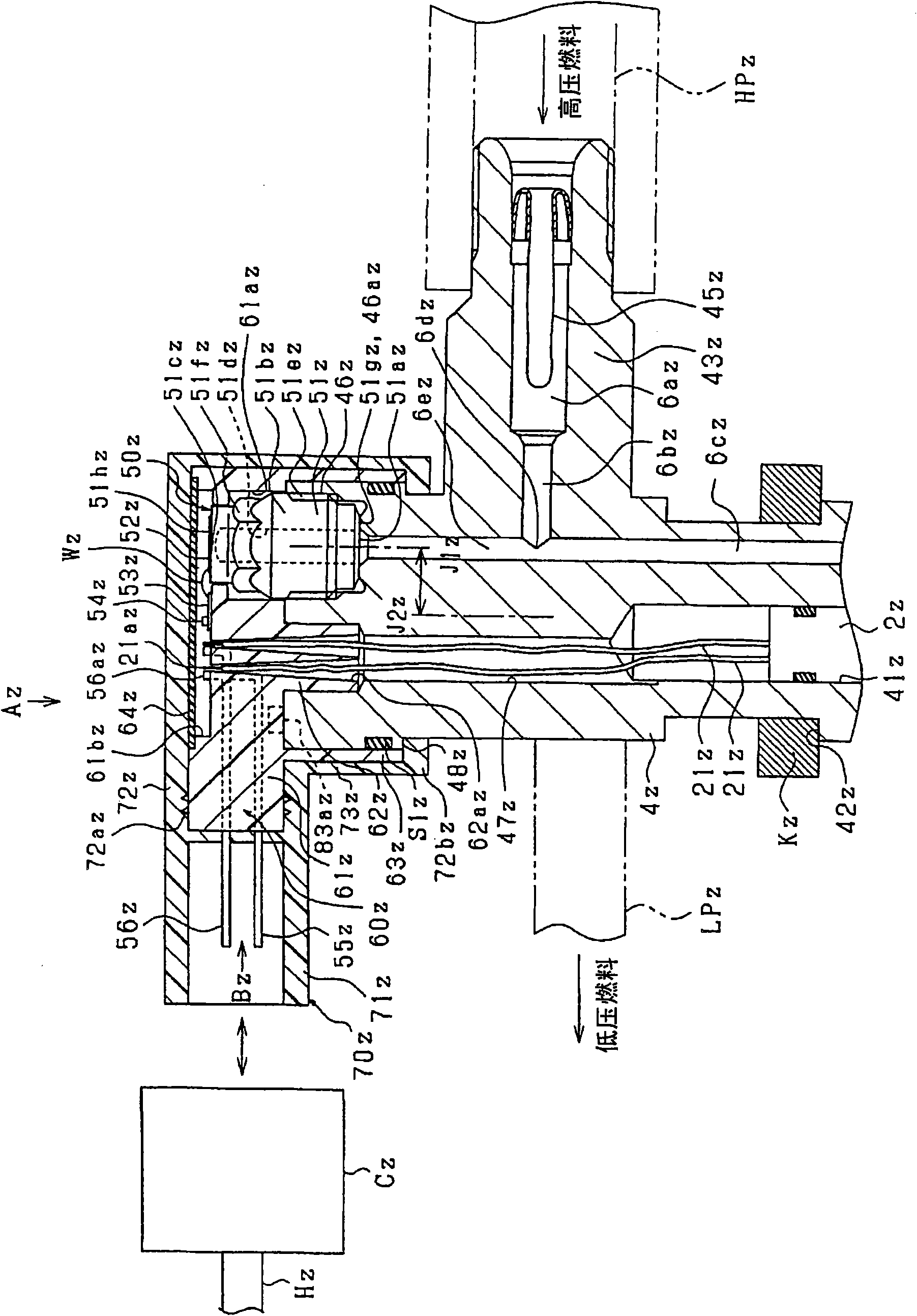
[0070] use figure 1 as well as figure 2 The first embodiment of the present invention will be described. figure 1 is a schematic cross-sectional view showing a schematic internal structure of an injector (fuel injection valve) according to this embodiment, figure 2 is a detailed description figure 1 magnified view of .

[0071] First, according to figure 1 The basic structure and operation of the injector will be explained. The injector injects high-pressure fuel accumulated in a common rail (not shown) into a combustion chamber Elz formed in a cylinder of a diesel internal combustion engine, and includes: a nozzle 1z that injects fuel when the valve is opened; A piezoelectric actuator 2z (opening and closing mechanism) that expands and contracts by charging and discharging, and a back pressure driving mechanism 3z (opening and closing mechanism) that is driven by the piezoelectric actuator 2z to control the back pressure of the nozzle 1z.

[0072] The nozzle 1z includ...

no. 2 approach

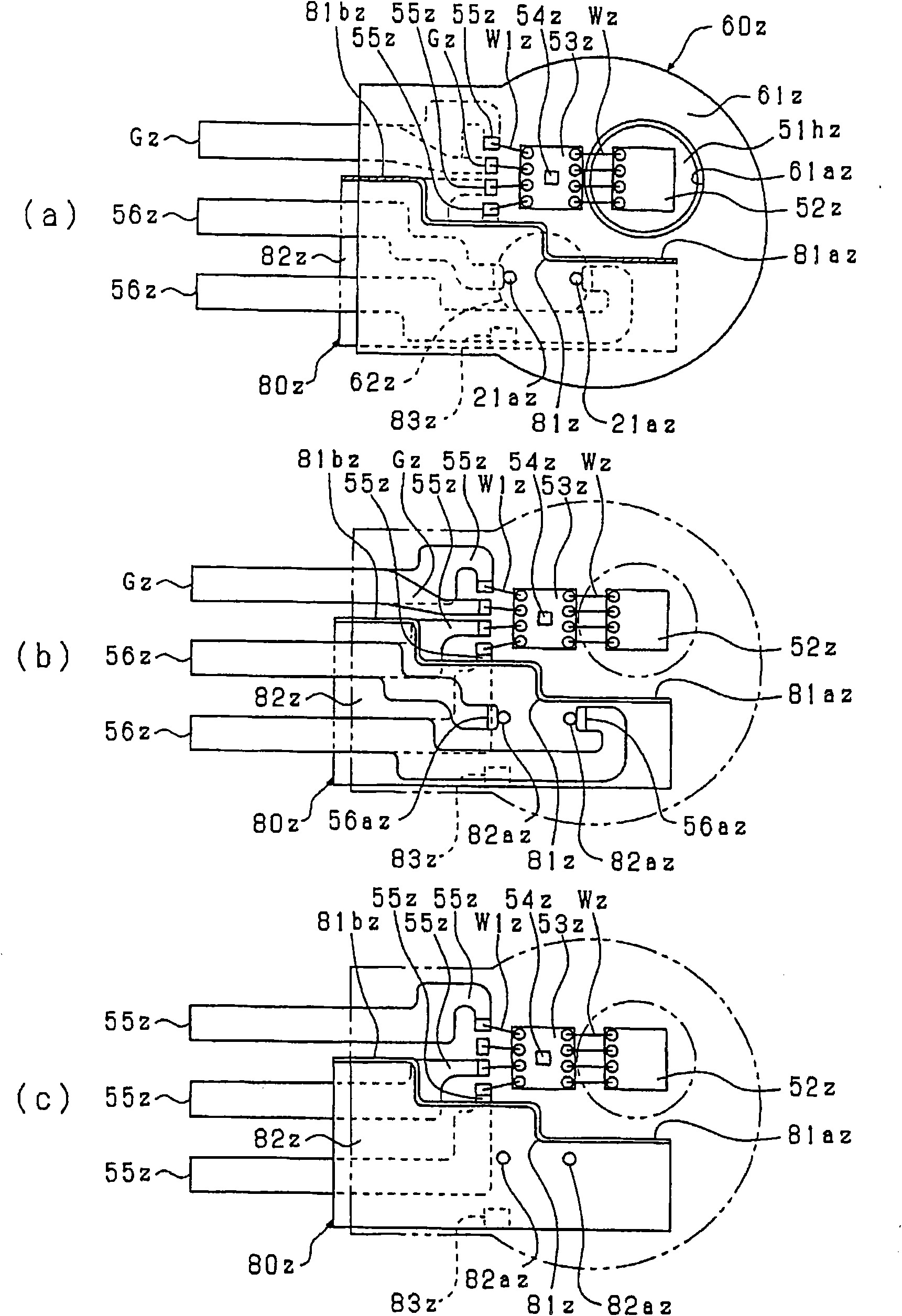
[0135] In the present embodiment, a memory chip Mz that stores a correction value for the pressure detection value detected by the fuel pressure sensor 50z (see Figure 5 ). Specifically, the deviation between the pressure detection value of the strain gauge 52z and the actual fuel pressure is acquired in advance through a test or the like, and the deviation is stored as a correction value in the memory chip Mz in advance, and a signal of the correction value is output to the outside such as the engine ECU. equipment. Accordingly, in the engine ECU, a correction value specific to the fuel pressure sensor 50z can be obtained, and the pressure detection value obtained from the fuel pressure sensor 50z can be corrected based on the obtained correction value.

[0136] In addition, one of the three sensor terminals 55z used in the first embodiment is used as the memory terminal 55z for outputting the correction value. Therefore, in addition to the drive terminal 56z, the sensor t...

no. 3 approach

[0139] The lead wires 21z of the piezoelectric actuator 2z and the fuel pressure sensor 50z are located inside the connector housing 70z, and these lead wires 21z and the fuel pressure sensor 50z need to be sealed from the outside of the connector housing 70z. Regarding this sealing structure, in the above-mentioned first embodiment, by disposing the O-ring S1z (sealing member) between the inner peripheral surface of the cylindrical portion 63z of the molded resin 60z and the outer peripheral surface of the main body 4z, one O-ring S1z The ring S1z seals both the lead wire 21z and the fuel pressure sensor 50z.

[0140] In contrast, in Image 6 In the present embodiment shown, the lead wire 21z and the fuel pressure sensor 50z each include different O-rings S2z and S3z (sealing members). Specifically, an O-ring S2z is disposed between the cylindrical portion 51bz of the fuel pressure sensor 50z and the recessed portion 46z of the molded resin 60z. In addition, an O-ring S3z i...


PUM


Abstract

A fuel injection valve has an injector body (4z) having formed in it high-pressure paths (6az, 6bz, 6cz) that allow high-pressure fuel to flow to a nozzle and receiving a piezo actuator (2z)(drive means) etc. for operating a needle (valve element) to open and close the nozzle; a fuel pressure sensor (50z) mounted on the body (4z) and detecting the pressure of the high-pressure fuel; a senor terminal (55z) for externally outputting the detected pressure value obtained from the fuel pressure sensor (50z); a drive terminal (56z) to which electric power for the piezo actuator (2z) is supplied; and a connector housing (70z) for holding the sensor terminal (55z) and the drive terminal (56z). The sensor terminal (55z), the drive terminal (56z), and the connector housing (70z) form a single connector.

Description

technical field [0001] The present invention relates to a fuel injection valve and a fuel injection device mounted on an internal combustion engine and injecting fuel from an injection hole. Background technique [0002] In order to control the output torque and emission state of the internal combustion engine with high precision, it is important to control the injection amount of fuel injected from the fuel injection valve, the injection start timing, and the injection method with high precision. Therefore, a technique has been proposed in which the actual injection method is detected by detecting the fuel pressure which fluctuates with the injection. [0003] For example, it is possible to detect the actual injection start timing by detecting the timing at which the fuel pressure starts to drop accompanying the injection, or to detect the actual injection amount by detecting the amount of drop in the fuel pressure associated with the injection. If the actual injection met...

Claims


Application Information

Patent Timeline
Patent Type & Authority Applications(China)
IPC IPC(8): F02M51/06F02D35/00F02M47/00F02M51/00F02M61/10
CPCF02M51/005F02M2200/24F02M47/027F02M57/005F02D41/2096F02M63/0026
Inventor 近藤淳田口透藤野友基有川文明山中昭利
Owner DENSO CORP
Why Eureka
Try Eureka