Non-contact measurement apparatus and method

A non-contact, imaging device technology, applied in the direction of measuring devices, camera devices, optical devices, etc., can solve the problems of high computing requirements, useless data and sensitivity to lighting artifacts

Inactive Publication Date: 2010-09-01
RENISHAW PLC
View PDF3 Cites 27 Cited by
  • Summary
  • Abstract
  • Description
  • Claims
  • Application Information

AI Technical Summary

Problems solved by technology

This technique can be used to recognize more complex shapes, but the required calculations are very demanding, and the results are sensitive to garbage data and lighting artefacts in the image

Method used


Image

  • Non-contact measurement apparatus and method
  • Non-contact measurement apparatus and method
  • Non-contact measurement apparatus and method

Examples


Embodiment Construction

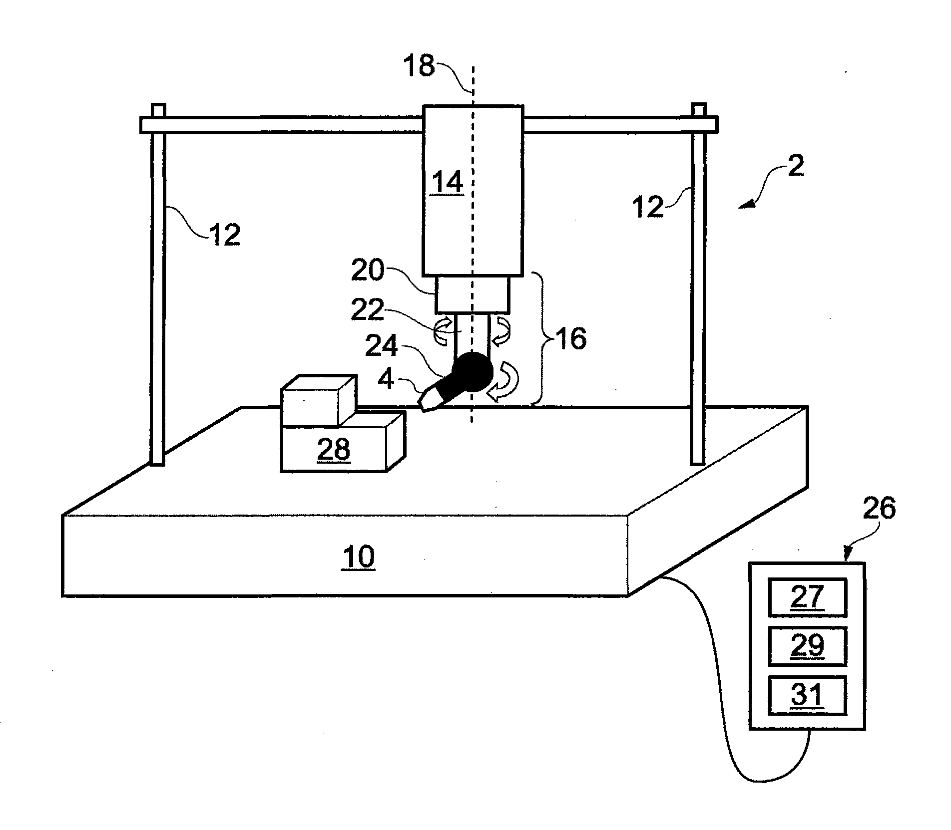
[0087] The CMM 2 includes a base 10 for supporting a frame 12 which in turn holds a spindle 14 . Motors (not shown) are arranged to move the spindle 14 along three mutually orthogonal axes X, Y and Z. The spindle 14 holds an articulation head 16 . The articulating head 16 has a base portion 20 attached to the main shaft 14 , a middle portion 22 and a probe holding portion 24 . The base portion 20 includes a first motor (not shown) for rotating the intermediate portion 22 about the first axis of rotation 18 . Intermediate portion 22 includes a second motor (not shown) for rotating probe holding portion 24 about a second axis of rotation that is substantially perpendicular to the first axis of rotation. Although not shown, bearings may be provided between movable parts of the joint 16 . Additionally, although not shown, measuring encoders may be provided to measure the relative positions of the base 10 , frame 12 , spindle 14 and articulation head 16 so that the position of t...


PUM


Abstract

A non-contact method and apparatus for inspecting an object. At least one first image of the object on which an optical pattern is projected, taken from a first perspective is obtained. At least one second image of the object on which an optical pattern is projected, taken from a second perspective that is different to the first perspective is obtained. At least one common object feature in each of the at least one first and second images is then determined on the basis of an irregularity in the optical pattern as imaged in the at least one first and second images.

Description

technical field [0001] The invention relates to a method and a device for measuring an object without touching the object. Background technique [0002] Photogrammetry is a known technique for determining the position of a particular point on an object from photographs taken at different viewpoints, ie from different positions and / or orientations. Typically, photogrammetry involves taking at least two images of an object from two different viewpoints. For each image, two-dimensional coordinates of object features in the image are determined. The three-dimensional coordinates of features on the object can then be determined from knowledge of the position and orientation of the camera that took the image and where the features are formed on the image. This technique is disclosed, for example, in US5251156, the entire content of which is incorporated herein by reference. [0003] In order to perform photogrammetry, it is necessary to identify features of an object that can b...

Claims


Application Information

Patent Timeline
Patent Type & Authority Applications(China)
IPC IPC(8): G01B11/00G01B11/25G01C11/02
CPCG01B11/2527G01B11/026G01B11/007G06T7/0057G06T7/0004G06T7/521G06T7/593G06T2207/30164
Inventor 尼古拉斯·约翰·韦斯顿伊冯娜·鲁思·赫德阿特安德鲁·约翰·穆尔
Owner RENISHAW PLC
Why Eureka
Try Eureka