Self-circulation cooling automobile brake drum device

A technology for automobile brakes and brake drums, which is applied in the direction of cooling brakes, brakes, and vehicle components, and can solve problems such as inability to play a cooling role, and achieve the effects of ensuring safety, saving water resources, and reducing high temperature

Inactive Publication Date: 2010-09-08
李智
View PDF4 Cites 13 Cited by
  • Summary
  • Abstract
  • Description
  • Claims
  • Application Information

AI Technical Summary

Problems solved by technology

Although this patent can be cooled without the cooling method of external spray water, it needs to be powered by a water pump and an engine battery. If the generator battery fails, the device cannot work and cannot play a cooling role at this time.

Method used


Image

  • Self-circulation cooling automobile brake drum device
  • Self-circulation cooling automobile brake drum device
  • Self-circulation cooling automobile brake drum device

Examples


Embodiment Construction

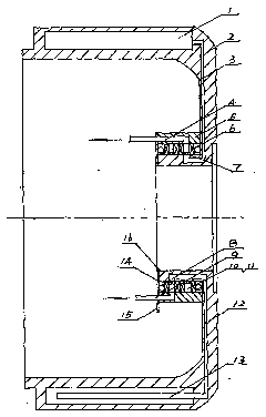
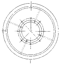
[0022] Such as figure 1 Shown, the automobile brake drum device of self-circulation cooling of the present invention, its composition is to be provided with water cooling chamber 1 and brake drum inlet water passage 12 and brake drum outlet water passage 3 on brake drum 2, and brake drum An inner ring 16 is connected, or the inner ring is integrated with the brake drum, such as figure 2 , 3 shown. Bearing 8, skeleton sealing ring 6, annular impeller 10, skeleton sealing ring, annular impeller, skeleton sealing ring, bearing are arranged on the inner ring in sequence, and an outer ring 5 (such as Figure 9 As shown), the direction of rotation of the two annular impellers is opposite, there are water inlet pipes 9 and water outlet pipes 4 on the outer ring, end covers 14 are provided on the end faces of the outer ring and inner ring, and there are positioning blocks connected with the automobile brake floor on the end covers 15. Such as Figure 6 , 7 , Shown in 8, the str...


PUM


Abstract

The invention discloses a self-circulation cooling automobile brake drum device, which is provided with a water cooling chamber and a water inlet and outlet channel on a brake drum, an inner ring is connected with the brake drum, the inner ring is sequentially provided with a bearing, a sealing ring, an annular impeller, a sealing ring, an annular impeller and a sealing ring bearing, and is sleeved with an outer ring, wherein the outer ring is provided with the water inlet and outlet channel, the end surfaces of the outer ring and the inner ring are provided with end covers, and the rotation directions of the two annular impellers are opposite. The cooling water of the self-circulation cooling automobile brake drum device can be recycled, and can not pollute the road, so the running safety of the automobile is ensured (i.e. the pollution of sprayed water on the road does not exist), high temperature generated when the automobile brake drum brakes is greatly reduced, and the water supply and drainage circulation of the cooling water in the brake drum is ensured.

Description

technical field [0001] The invention relates to an automobile brake device, in particular to a self-circulation cooling automobile brake drum device. Background technique [0002] The existing steam wheel brake drum adopts the cooling mode of external spraying water to cool. However, the disadvantage of this method is that it causes damage and slipperiness of the road, causing potential safety hazards for light vehicles, and poor cooling effect during braking. Patent No. 93239119.2 utility model patent discloses a "vehicle brake cooling device". The device is fixed on the bottom plate of the automobile brake with a flow distributor, and the cooling liquid is sent to the flow distributor that does not rotate with the wheels through the radiator through the radiator liquid outlet pipe. The liquid inlet channel of the outer ring flows into the liquid inlet channel of the inner ring of the distributor that rotates with the wheel through the gap of the sealing ring that does not...

Claims


Application Information

Patent Timeline
IPC IPC(8): B60T5/00
Inventor 李智
Owner 李智
Why Eureka
Try Eureka