Bridge erecting machine for bridge erection

A bridge erection machine and bridge technology, applied in bridge construction, bridges, erection/assembly of bridges, etc., can solve the problems of low speed, reduced curvature radius, unable to meet the erection of urban rail beams, etc. The effect of fast speed and high beam erection efficiency

Inactive Publication Date: 2010-09-08
ZHENGZHOU HUAZHONG CONSTR MACHINERY CO LTD
View PDF3 Cites 1 Cited by
  • Summary
  • Abstract
  • Description
  • Claims
  • Application Information

AI Technical Summary

Problems solved by technology

The speed of urban rail transit is lower than that of high-speed rail, and the corresponding radius of curvature is also reduced and much, and some sections are even smaller than m, which makes the equipment for erecting high-speed rail beams unable to meet the erection of urban rail beams.

Method used


Image

  • Bridge erecting machine for bridge erection
  • Bridge erecting machine for bridge erection
  • Bridge erecting machine for bridge erection

Examples


Embodiment Construction

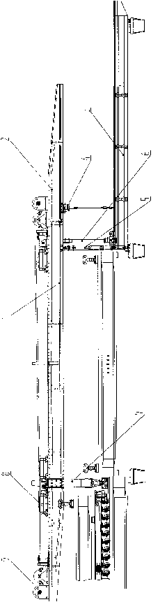
[0038] Such as figure 1 As shown, the present invention includes a main beam assembly (1), a cantilever beam (2) arranged at the front end of the main beam assembly (1), and a lower guide beam assembly (3) arranged at the lower part of the main beam assembly (1) ), characterized in that: an auxiliary trolley (4) is arranged on the cantilever beam (2), a front outrigger assembly (5) is arranged at the front end of the main beam assembly (1), and a front leg assembly (5) is arranged on the main beam assembly (1) An auxiliary outrigger (6) is set between the lower guide beam assembly, a rear outrigger assembly (7) is set at the rear of the main beam assembly (1), and a Lifting trolley (8) and the hoisting device (9) that is connected with lifting trolley (8).

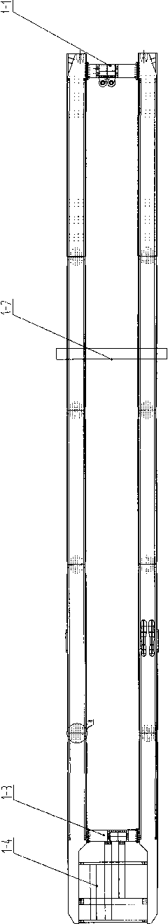
[0039] Such as figure 2 , 3 As shown, the main beam assembly (1) adopts a double box girder structure, and a front beam (1-1) is fixed by bolts between the front end double box girders of the main beam assembly (1). B...


PUM


Abstract

The invention belongs to the field of bridge erection, particularly relating to a small-curve bridge erecting machine for bridge erection for railways. The bridge erecting machine for bridge erection comprises a girder assembly, a cantilever beam arranged on the front end of the girder assembly and a lower guide beam assembly arranged on the lower part of the girder assembly, wherein an assistant trolley is arranged on the cantilever beam; the front end of the girder assembly is provided with a front landing leg assembly, an assistant landing leg is arranged between the girder assembly and the lower guide beam assembly, the rear part of the girder assembly is provided with a rear landing leg assembly, and the upper part of the girder assembly is provided with a hoisting trolley and a winch connected with the hoisting trolley. The invention has high bridge erection efficiency and high hole passing speed; low guide beam causes that the guide beam can bear bigger yawing force to ensure that the bridge erecting machine is safer to pass through the hole; large assistant crown block shift amount can erect the beam with smaller curvature radius; a rear landing leg running slide plate can reduce bridge erecting machine running resistance and prevent the running mechanism from being damaged.

Description

technical field [0001] The invention belongs to the field of bridge erecting, and in particular relates to a bridge erecting machine for small curved railway bridges. Background technique [0002] With the rapid development of high-speed rail, urban rail transit has also developed rapidly. The speed of urban rail transit is lower than that of high-speed rail, and the corresponding radius of curvature is also reduced and much, and some sections are even smaller than m, which makes the equipment for erecting high-speed rail beams unable to meet the erection of urban rail beams. In response to this situation, our company invented a bridge erecting machine capable of erecting line girders with small curvature radius through partial transformation of high-speed railway bridge machines. Contents of the invention [0003] The purpose of the present invention is to overcome the deficiencies in the prior art and provide a bridge erecting machine which is convenient for passing hol...

Claims


Application Information

Patent Timeline
Patent Type & Authority Applications(China)
IPC IPC(8): E01D21/06
Inventor 宋鹏伟陶英喜王艳芳王荣芝黄远方秦宏义
Owner ZHENGZHOU HUAZHONG CONSTR MACHINERY CO LTD
Why Eureka
Try Eureka