Storing and lifting device and method for U-shaped beam

A U-shaped, cross-beam technology, applied in the direction of hoisting equipment braking devices, hoisting devices, transportation and packaging, etc., can solve the problems of wasting beam storage space, high construction costs, limited space, etc., to improve the efficiency of beam erection, structure Simple and convenient storage and withdrawal methods

Pending Publication Date: 2021-01-05
船东物联江苏有限公司
View PDF0 Cites 0 Cited by
  • Summary
  • Abstract
  • Description
  • Claims
  • Application Information

AI Technical Summary

Problems solved by technology

[0004] In the process of beam erection, in order to meet the requirements of the construction period, temporary beam storage points are often set up at the beam erection points. The space for temporary beam storage points is limited. If the tire type beam lifting machine or truck is used for lifting, the beam storage space will be wasted and the construction cost will be high.

Method used


Image

  • Storing and lifting device and method for U-shaped beam
  • Storing and lifting device and method for U-shaped beam
  • Storing and lifting device and method for U-shaped beam

Examples


Embodiment Construction

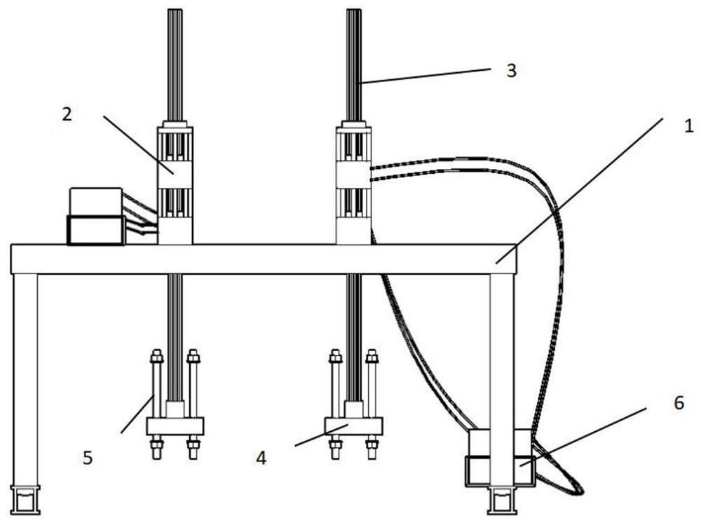
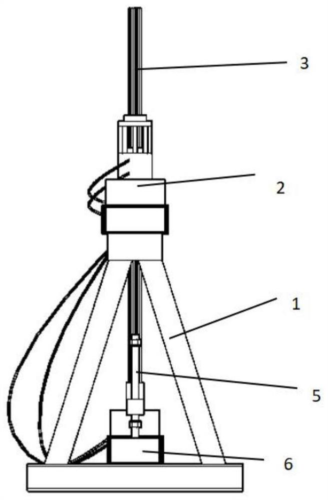
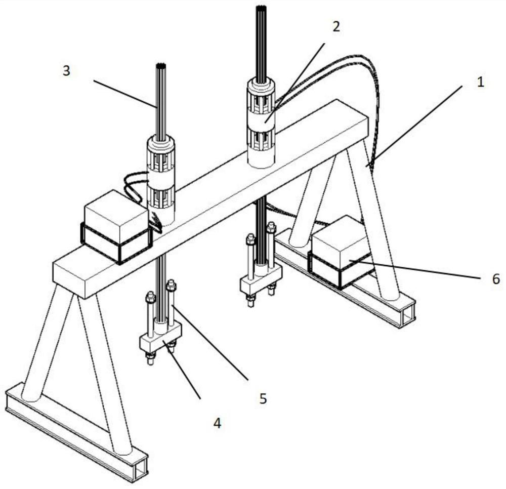
[0023] Such as Figure 1 to Figure 3 As shown, the storage and withdrawal device of the U-shaped beam of the present invention includes a plurality of storage and withdrawal units. In each storage and withdrawal unit, 1 is a door frame, which is in the shape of a "gate" as a whole; 2 is a continuous jack; 3 is a steel strand Line; 4 is a spreader; 5 is a positioning pin; 6 is an oil pump.

[0024] The overall door frame is in the shape of a "door". The door frame includes a beam, a beam pillar assembly and a bottom beam, and the beam and bottom beam are connected by a beam pillar assembly. The crossbeam pillar assembly is fixed by two crossbeams, and the crossbeam pillar assembly and the bottom beam form a triangular structure to ensure the stability of the overall structure. There are lifting lugs at both ends of the beam, and the transfer of the device can be realized by hoisting the car.

[0025] Two continuous jacks 2 are vertically welded on the beams of the front and r...


PUM


Abstract

The invention discloses a storing and lifting device and method for a U-shaped beam. The storing and lifting device comprises a plurality of storing and lifting units; each storing and lifting unit comprises a portal, jacks, lifting appliances, steel strands and an oil pump; each portal comprises a cross beam, cross beam supporting column assemblies and a bottom beam, wherein each cross beam is connected with the bottom beams through the cross beam supporting column assemblies; the jacks are fixed to the cross beams, the oil pumps provide power for the jacks, and the jacks drive the lifting appliances to lift through the steel strands; and the lifting appliances are fixedly connected with the U-shaped beam. Each cross beam supporting column assembly is formed by fixing two cross beams in acrossed manner, and each cross beam supporting column assembly and each bottom beam form a triangular structure. During storing and lifting, the storing and lifting units are moved to the two ends ofthe U-shaped beam through a crane, the jacks are controlled through the oil pumps to lower the lifting appliances to the positions of U-shaped beam lifting holes, lifting appliance positioning pins are fixed to the U-shaped beam body lifting holes, and the jacks are controlled to lift the lifting appliances so as to lift the U-shaped beam. According to the storing and lifting device and method, the movement is completed through a single small crane, the site utilization is maximized while the hoisting cost is saved, and the beam erecting efficiency is improved.

Description

technical field [0001] The invention relates to U-shaped beams, in particular to a storage and withdrawal device and storage and withdrawal method for U-shaped beams. Background technique [0002] The U-shaped beam belongs to a bottom-loaded bayonet thin-walled structure. The beam body is connected by the bottom plate, the webs on both sides and the flange plate on the top of the web to form a U-shaped cross-section channel. The upper surface of the bottom plate is connected to the supporting rail. The platform, the train runs on the rail platform of the floor and is wrapped in the U-shaped beam. [0003] The commonly used spans of U-shaped beams are 25 meters, 30 meters and 35 meters, and the spans are large. At present, when lifting the beams in the beam yard, a tire-type special beam lifting machine or two cranes are used to lift the beams, which requires a large working space and high lifting costs. [0004] In the process of beam erection, in order to meet the require...

Claims


Application Information

Patent Timeline
Patent Type & Authority Applications(China)
IPC IPC(8): B66C5/02B66C1/66
CPCB66C1/66B66C5/02
Inventor 邓新
Owner 船东物联江苏有限公司
Why Eureka
Try Eureka