Method and device for realizing quick rerouting

A routing, fast technology used in the field of communications

Inactive Publication Date: 2010-09-08
ZTE CORP
View PDF3 Cites 13 Cited by
  • Summary
  • Abstract
  • Description
  • Claims
  • Application Information

AI Technical Summary

Problems solved by technology

[0007] In view of the above analysis, the present invention aims to provide a method and device for realizing fast rerouting, to solve the problem that the existing fast rerouting meth

Method used


Image

  • Method and device for realizing quick rerouting
  • Method and device for realizing quick rerouting
  • Method and device for realizing quick rerouting

Examples


Embodiment Construction

[0038] Preferred embodiments of the present invention will be specifically described below in conjunction with the accompanying drawings, wherein the accompanying drawings constitute a part of the application and are used together with the embodiments of the present invention to explain the principle of the present invention. For the sake of clarity and simplicity, detailed descriptions of known functions and constructions in the devices described herein will be omitted when it may obscure the subject matter of the present invention.

[0039] first combined with figure 1 to attach Image 6 The method of the present invention is described in detail.

[0040] like figure 1 as shown, figure 1 It is a schematic flow diagram of the main process of the method of the present invention, which may specifically include the following steps:

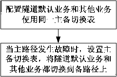
[0041] Step 101: Configure the tunnel default service and other services to use the same master-standby switchover table; specifically, during ...


PUM


Abstract

The invention discloses a method and for realizing quick rerouting. The method comprises the following steps: configuring a tunnel default service and other services, which use the same main/standby switching table; and detecting whether the state of the main route is normal; and when confirming that the main route breaks down, setting the main/standby switching table, and switching the tunnel default service and the other services to a selected standby route. The invention can ensure that all the services borne by the tunnel can be quickly switched within the performance requirement range, and greatly reduces the load on the control plane of the tunnel.

Description

technical field [0001] The present invention relates to the technical field of communications, in particular to a method and device for realizing fast rerouting. Background technique [0002] FRR (Fast ReRoute, fast rerouting) technology is a mechanism to protect links and nodes. It protects the main path through the backup path. When the primary path fails, the data traffic on the primary path is quickly switched to the backup path. To ensure the continuous flow of business data. [0003] At present, the application of FRR in network tunnel technology has the following implementation methods: [0004] Method 1: Rewrite the forwarding table information, that is, update the forwarding information of the primary path to the forwarding information of the backup path, so as to realize FRR. The defect of this method is: in the process of updating the forwarding information, there are data streams because the forwarding information is incomplete. Packet loss may even cause excep...

Claims


Application Information

Patent Timeline
IPC IPC(8): H04L12/56H04L12/24
CPCH04L45/50H04L45/28H04L45/22
Inventor 钱勇孙蓓
Owner ZTE CORP
Why Eureka
Try Eureka